
Circuit Diagram
Index 334
Delay circuit with NE555 timer
Published:2012/9/13 21:43:00 Author:Ecco | Keyword: Delay circuit , timer

This circuit design was used to switch on device via a LED photocell arrangement (optocoupler) using components R1, C1, D1 and Q1. It produces a delay on powering up to ensure correct sequencing of certain equipment. A very simple delay timer using a single transistor and an R-C timing circuit. (View)
View full Circuit Diagram | Comments | Reading(4321)
Binary Counter using 555 and 4042B
Published:2012/9/13 21:29:00 Author:Ecco | Keyword: Binary Counter
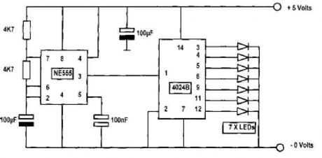
In this circuit diagram, an NE555 timer is used as a pulse generator producing pulses at about one-second duration. This is governed by the timing components connected to pins 2, 6, and 7. If the 100μF capacitor connected on pins 2 and 6 were reduced to 47μF, then the counting pulses will be about 1/2 second each. The output of the pulse generator at pin 3 is connected to pin 1 of the binary counter 4042B. The actual device is a 4042 but are usually advertised as CD4042BE, CD 4042BM, CD 4042BC and so on, but as far as we are concerned in this application they are all the same and will give the same results..... (View)
View full Circuit Diagram | Comments | Reading(3155)
Car windshield wiper delay
Published:2012/9/13 21:26:00 Author:Ecco | Keyword: Car, windshield wiper, delay

The circuit provides a windshield wiper delay, dynamic braking and windshield wipers when they reach the rest position. This prevents the blades passing, which could lead them to stop at a point where they interfere with the vision of drivers. With the original wiper switch off, switch turns on the MLS delay circuit and disconnects the wiring SIB from automobiles. When SI is turned off, the original wiring system and controls the delay circuit is bypassed.
(View)
View full Circuit Diagram | Comments | Reading(2718)
CAR IMMOBILIZER CIRCUIT
Published:2012/9/13 21:25:00 Author:Ecco | Keyword: CAR IMMOBILIZER

A flip of 51 puts the system in action. Power for the circuit is captured from the ignition switch, and circuit receives no power until the ignition switch is closed. When the camera is turned on, the capacitor C1 is charged and the emitter follower Darlington pair (formed by Q1 and Q2) are cut, so no voltage is applied to the relay (Kl), which serves as a load QL transmitter. normally open relay contacts are connected through the points of the vehicle. (At this point, the relay contacts are open and have no effect on the ignition system). Cl charges through R, causing the voltage at the base of Ql to rise steadily.
Source: NEXT.GR (View)
View full Circuit Diagram | Comments | Reading(3164)
Car Wiper-Speed Controller
Published:2012/9/13 21:22:00 Author:Ecco | Keyword: Car, Wiper-Speed Controller

This 12V wiper speed controller circuit uses the 555 timer. And can be fitted to any car. Its one of those very easy and usefull circuits! (View)
View full Circuit Diagram | Comments | Reading(2431)
IR Motion Detector alarm
Published:2012/9/13 21:22:00 Author:Ecco | Keyword: IR Motion Detector , alarm

This type of motion detector uses the same basic concept as the active infrared motion detector. An interruption in a 5 kHz modulated pulsating beam that is transmitted by an infrared diode and received by an infrared transistor sets off the alarm.
Source: NEXT.GR (View)
View full Circuit Diagram | Comments | Reading(1633)
Metal Detector TDA 2822
Published:2012/9/13 21:17:00 Author:Ecco | Keyword: Metal Detector
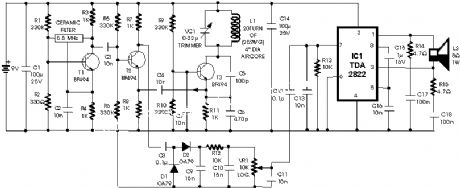
The circuit described here is that of a metal detector. The opera- tion of the circuit is based on superheterodyning principle which is commonly used in superhet receivers. The circuit utilises two RF oscillators. The frequencies of both oscillators are fixed at 5.5 MHz. The first RF oscillator comprises transistor T1 (BF 494) and a 5.5MHz ceramic filter commonly used in TV sound-IF section. The second oscillator is a Colpitts oscillator realised with the help of transistor T3 (BF494) and inductor L1 (whose construction details follow) shunted by trimmer capacitor VC1.
(View)
View full Circuit Diagram | Comments | Reading(2444)
Low cost Metal Detector
Published:2012/9/13 21:17:00 Author:Ecco | Keyword: Low cost , Metal Detector
Metal detectors are usually very complicated and it may be consist of very costly components and metal detector DIY circuits are rare. However this metal detector hobby circuit can be constructed by only a few components such as BC548 and an ordinary AM radio that we usually use.
Source: NEXT.GR (View)
View full Circuit Diagram | Comments | Reading(2022)
metal detector with MC AT90S2313
Published:2012/9/13 21:16:00 Author:Ecco | Keyword: metal detector , MC

It's a simple metal detector design that has the quite good characteristics. the principle of operation which one differs from the classic schemes (BFO, transmit-receive known as two-boxes metal detector, inductive). The dynamic mode is used to find targets in interference environment. There is known from theory of signal filtration that if signal shape is determined we can construct optimal filter - the best one for extracting the signal with maximum signal/noise ratio. This filter is known as optimal matched filter.
(View)
View full Circuit Diagram | Comments | Reading(5609)
Metal detector with CD4011
Published:2012/9/13 21:16:00 Author:Ecco | Keyword: Metal detector
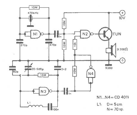
The working principle of this cheap and easy to build metal detector circuit consists in mixing two equal frequencies which causes a low-frequency interference. When one of the oscillators become unstable then the frenquency of the interference will be modified. The metal detector circuit is built with CD4011.
Source: NEXT.GR (View)
View full Circuit Diagram | Comments | Reading(3360)
BFO Metal Detector using LF347N
Published:2012/9/13 21:14:00 Author:Ecco | Keyword: BFO Metal Detector
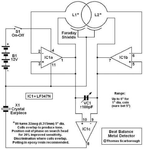
Here's a metal detector circuit that frequencies of the two oscillators are then mixed in similar fashion to BFO, to produce an audible heterodyne. On the surface of it, this design would seem to represent little more than a twinned BFO metal detector.
(View)
View full Circuit Diagram | Comments | Reading(3853)
Simple metal detector with 4011
Published:2012/9/13 21:14:00 Author:Ecco | Keyword: Simple metal detector
This simple metal detector requires only a handful of components and an evening's work. Built around a cmos4011 IC, is very robust and versatile. The 250 kHz reference oscillator is built with two gates (U1/1 and U1/2), C1, R1 and P1. The search oscillator uses only one gate (U1/3), two capacitors and the search coil. The outputs of the two oscillators are fed to the fourth gate acting as a mixer and filtered with C4. (View)
View full Circuit Diagram | Comments | Reading(1606)
Metal detector circuit with CS209A
Published:2012/9/13 21:13:00 Author:Ecco | Keyword: Metal detector

This circuit is a Single chip metal detector.Actually we can use this one to detect metals.Specially,I think you have seen some army soldiers keep some thing to detect metals.That equipment has been made through this circuit.so you also can use this to detect metals even bombs.
Source: NEXT.GR (View)
View full Circuit Diagram | Comments | Reading(3427)
Metal locator with Ic4093
Published:2012/9/13 21:13:00 Author:Ecco | Keyword: Metal locator
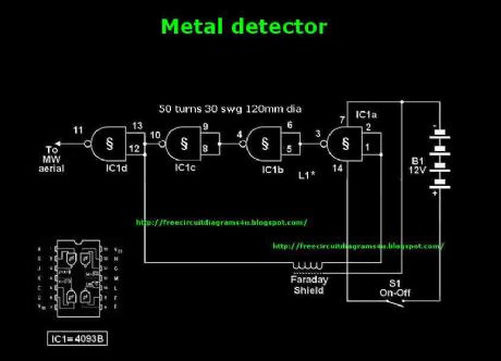
This circuit needs a a Faraday shield, which is connected to 0V.To make this one wrap a tin foil around the coil.and connect to 0v.Then you can use this circuit for find metal.Tune your mw radio until whistle sound comes.
Source: NEXT.GR (View)
View full Circuit Diagram | Comments | Reading(1640)
Single transistor Metal Detector circuit
Published:2012/9/13 21:12:00 Author:Ecco | Keyword: Single transistor, Metal Detector

The circuit is an oscillator and the way it keeps oscillating is due to positive feedback. This is the case with all oscillators and the component that provides the feedback is the 1n capacitor between the collector and emitter of the transistor. It may seem unusual that the transistor can be turned on via the emitter to keep it oscillating, but in fact it does not matter if the emitter or base receives a signal as the important factor is THE VOLTAGE DIFFERENCE between these two terminals.
Source: NEXT.GR (View)
View full Circuit Diagram | Comments | Reading(2286)
Zero beating Metal Detector
Published:2012/9/13 21:11:00 Author:Ecco | Keyword: Zero beating, Metal Detector
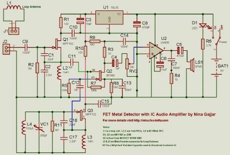
Both oscillators are built using MPF102 or J310 FETs. The Mixer is BF998 dual gate MOSFET. Audio IC amplifier is LM386 which drives a speaker. I have used a stabilized supply for two oscillators and mixer. U1, a 78L05 is doing this job nicely.
Source: NEXT.GR (View)
View full Circuit Diagram | Comments | Reading(3035)
Pulsed Induction Metal Detector
Published:2012/9/13 21:11:00 Author:Ecco | Keyword: Pulsed Induction, Metal Detector
As you can see, there is only one regulated 12 volt supply operating the entire circuit. I was able to do this simply by AC coupling the received signal to U3 via C10. This allowed me to adjust the offset within an operating window. By using a tantalum capacitor of reasonably high capacity, the signal passes with no problems. See Waveforms and Adjustments. This met my first goal.
Source: NEXT.GR (View)
View full Circuit Diagram | Comments | Reading(1416)
Metal Detector using (Beat Frequency)
Published:2012/9/13 21:10:00 Author:Ecco | Keyword: Metal Detector , Beat Frequency

When the signal with a frequency generated by the series of the search coil oscillator oscilator in with the mix-signal blocks of the Beat Frequency Oscilator akan produce a signal with a frequency difference of both frequency and this signal can be heard by human hearing. Voice vote which resulted as beat with a certain rhythm, and often known as the beat note. Changes in frequency depending on the size of the metal detected and the distance between the sensor with a metal detected. Rhythm beat and when this has been strengthened with the amplifier can be connected to a small spekaer beat to listen to the rhythm produced.
Source: NEXT.GR (View)
View full Circuit Diagram | Comments | Reading(1569)
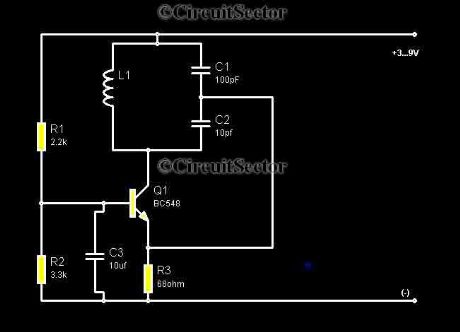
The simplest Metal detector with one BC548
Published:2012/9/13 21:10:00 Author:Ecco | Keyword: simplest, Metal detector, one
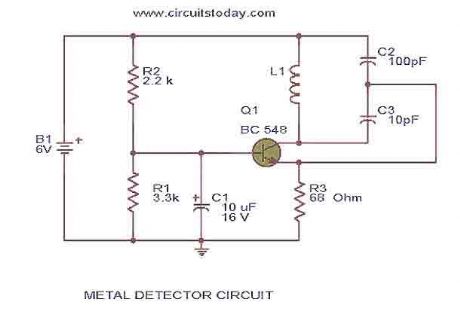
This is the circuit diagram of a low cost metal detector using a single transistor circuit and an old pocket radio..This is nothing but a Colpitts oscillator working in the medium band frequency and a radio tuned to the same frequency.First the radio and the circuit are placed close.Then the radio is tuned so that there is no sound from radio.In this condition the radio and the circuit will be in same frequency and same frequencies beat off to produce no sound.
Source: NEXT.GR (View)
View full Circuit Diagram | Comments | Reading(3637)
One Transistor Metal Detector
Published:2012/9/13 21:09:00 Author:Ecco | Keyword: One Transistor , Metal Detector

This is the design of simple circuit diagram of a low cost metal detector using a single transistor circuit and an old pocket radio. This is nothing but a Colpitts oscillator working in the medium band frequency and a radio tuned to the same frequency. This is the figure of the circuit.
Source: NEXT.GR (View)
View full Circuit Diagram | Comments | Reading(1864)
| Pages:334/2234 At 20321322323324325326327328329330331332333334335336337338339340Under 20 |
Circuit Categories
power supply circuit
Amplifier Circuit
Basic Circuit
LED and Light Circuit
Sensor Circuit
Signal Processing
Electrical Equipment Circuit
Control Circuit
Remote Control Circuit
A/D-D/A Converter Circuit
Audio Circuit
Measuring and Test Circuit
Communication Circuit
Computer-Related Circuit
555 Circuit
Automotive Circuit
Repairing Circuit