
Circuit Diagram
Index 335
Zero beat Metal detector
Published:2012/9/13 21:08:00 Author:Ecco | Keyword: Zero beat, Metal detector
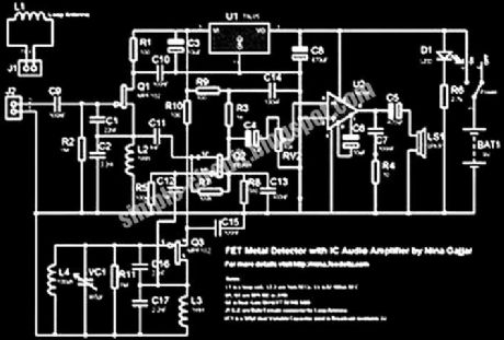
This is the design circuit for a sensing the metal. Metal detectors have two oscillators. One is tunable and the other is Fix with a loop. Both are Tuned at same frequency. Outputs from this two oscillators are then mixed in a mixer which produces only the difference. Means, if both oscillators are at the same frequency, there is nothing heard in the speaker. This is the figure of the circuit.
Source: NEXT.GR (View)
View full Circuit Diagram | Comments | Reading(1709)
Beat Balance Metal Detector
Published:2012/9/13 21:07:00 Author:Ecco | Keyword: Beat Balance, Metal Detector
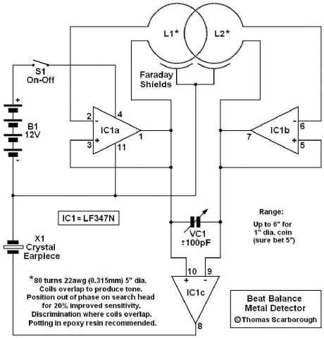
Various embodiments of the BB metal detector have been published, and it has been widely described in the press as a new genre. Instead of using a search and a reference oscillator as with BFO, or Tx and Rx coils as with IB, it uses two transmitters or search oscillators with IB-style coil overlap. The frequencies of the two oscillators are then mixed in similar fashion to BFO, to produce an audible heterodyne. On the surface of it, this design would seem to represent little more than a twinned BFO metal detector.
Source: NEXT.GR (View)
View full Circuit Diagram | Comments | Reading(1273)
Small Metal detector schematic circuit
Published:2012/9/13 21:07:00 Author:Ecco | Keyword: Small Metal detector
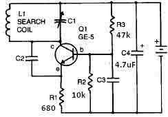
This metal detector circuit needs to be powered using a 9 volts power supply ( DC) or a 9 volts battery . The C1 capacitor is a variable capacitor with a value of 365 pF , C2 is a 100pF silver mica capacitor , C3 is a 0.05 uF disc capacitor and the C4 is a 4.7 uF capacitor . The Q1 transistor can be RCA SK3011 npn transistor or equivalent type and all resistors need to be ? watts.
Source: NEXT.GR (View)
View full Circuit Diagram | Comments | Reading(2553)
BFO metal Detector Circuit
Published:2012/9/13 21:07:00 Author:Ecco | Keyword: BFO, metal Detector

By adjusting the oscillators so their frequencies are very nearly the same, the difference between them is made audible as a beat note, this beat note changes slightly when the search loop is moved over or near to a piece of metal. It has been found in practice best to make the search oscillator fixed say at 100khz and to arrange for the reference oscillator to be adjustable 100khz plus or minus 250hz. This gives a beat note of 250hz to 0 to 250hz. The beat note disappears or nulls when the two oscillators are about equal. This type of detector is most sensitive when the beat note is close to zero, about 5hz ( motor boating ) any slight change being noticeable.
Source: NEXT.GR (View)
View full Circuit Diagram | Comments | Reading(3085)
BFO metal Detector Circuit with IC 4093
Published:2012/9/13 21:06:00 Author:Ecco | Keyword: BFO, metal Detector, IC
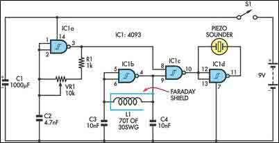
The circuit incorporates two oscillators, both operating at about 40kHz. The first, IC1a, is a standard CMOS oscillator with its frequency adjustable via VR1. The frequency of the second, IC1b, is highly dependent on the inductance of coil L1, so that its frequency shifts in the presence of metal. L1 is 70 turns of 0.315mm enamelled copper wire wound on a 120mm diameter former.
Source: NEXT.GR (View)
View full Circuit Diagram | Comments | Reading(5132)
Bifilar oscillator metal detector
Published:2012/9/13 21:05:00 Author:Ecco | Keyword: Bifilar oscillator, metal detector

Its performance is not comparable to more advanced commercial products, of course, but it still works. Anyway, during WWII metal detectors based on the same principle were utilized my combat engineers of many armies to clear mines. The main idea is really quite simple: build two identical oscillators and adjust them to the same frequency. One of the oscillators uses the search coil while the second one incorporates a variable inductor. When both are operating at the same frequency, the output is zero. If the search coil moves near any metal, however, frequency of the first oscillator shifts and an audible tone is heard in the headphones.
Source: NEXT.GR (View)
View full Circuit Diagram | Comments | Reading(1264)
Mini metal detecror (colpitts oscillator)
Published:2012/9/13 21:04:00 Author:Ecco | Keyword: Mini, metal detecror, colpitts oscillator
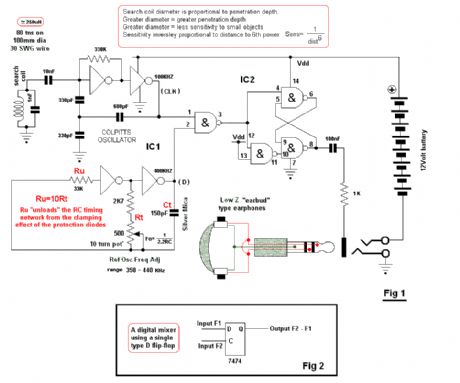
The circuit uses two CMOS IC’s IC1 uses inverters connected as a Colpitts oscillator of 100KHz; the LC frequency determining elements being the search coil and parallel resonating capacitor. An 80 turn close wound 30swg 100mm diameter coil will fit inside the CD case. I will leave the choice of the IC to the reader: this can be any of the well known CMOS inverters or NAND, NOR gates etc configured as an inverters. The choice is yours, use whatever you have on hand. IC2 can be either 74C00 or 4011 quad NAND gates.
Source: NEXT.GR (View)
View full Circuit Diagram | Comments | Reading(2417)
Simple Metal Detector
Published:2012/9/13 21:04:00 Author:Ecco | Keyword: Simple , Metal Detector
The Meter and other small circuit differences, gives better performance. On the Schematic, I show Two Possible Coils. 1) The Ferrite Rod, creates an Accurate Pin Point. But it also has a Very Narrow Detection Field. 2) The Dual Wound Tesla Coil Creates a Wide Field of Detection. With Maximum Sensitivity at the Center of the coil. Detection of metal is with a Meter and LED. The Meter Gives a Much Better Sensitivity.
Source: NEXT.GR (View)
View full Circuit Diagram | Comments | Reading(1061)
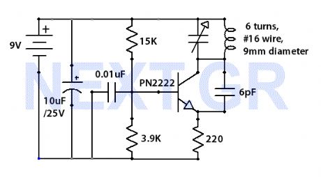
TV and FM jammer schematic
Published:2012/9/13 20:59:00 Author:Ecco | Keyword: TV, FM jammer

The Jammer is a very small circuit and can fit inside a small plastic box with 9V battery inside. It can be very illegal if you attach an external antenna so don't. adjust frequency by turning trimmer.
Source: NEXT.GR (View)
View full Circuit Diagram | Comments | Reading(0)
FM radio with TDA7000
Published:2012/9/13 20:58:00 Author:Ecco | Keyword: FM radio
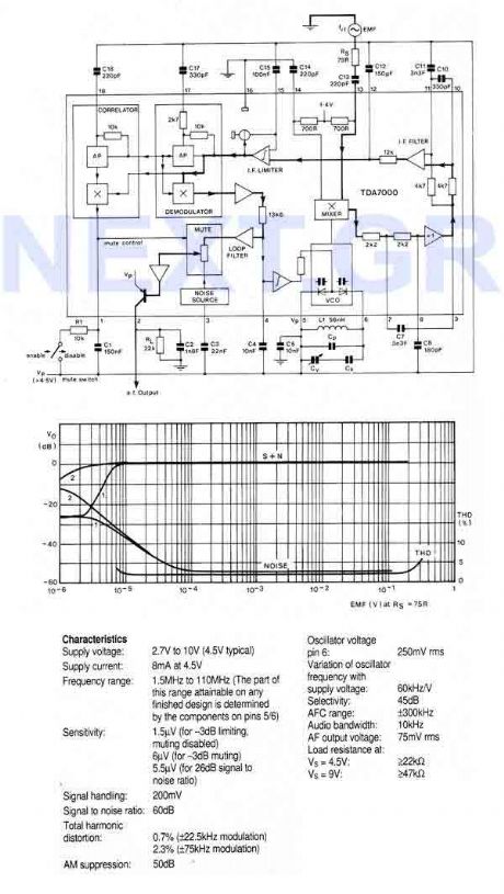
An FM radio on a single chip requiring only a few simple peripheral components. In particular the ship requires only one simple coil and alignment is very easy. The chip includes an RF input stage, mixer, local oscillator, IF amplifier/limiter, phase demodulator, mute detector and mute switch. The output will directly drive a crystal earpiece or could be used with a TBA820M to form a complete portable radio.
Source: NEXT.GR (View)
View full Circuit Diagram | Comments | Reading(2343)
1W Linear FM Booster
Published:2012/9/13 20:55:00 Author:Ecco | Keyword: 1W, Linear FM Booster

That RF Amplifier is for boosting small fm transmitters and bugs. It use two Philips 2N4427 and its power is about 1Watt. At the output you can drive any linear with BGY133 or BLY87 and so on. Its power supply has to give 500mA current at 12 Volts. More voltage can boost the distance but the transistors will be burned much earlier than usual.! In any case do not exceed the 15Volts.
Source: NEXT.GR (View)
View full Circuit Diagram | Comments | Reading(1241)
1W stereo Headphone Amp (TDA2822)
Published:2012/9/13 20:54:00 Author:Ecco | Keyword: 1W , stereo Headphone Amp
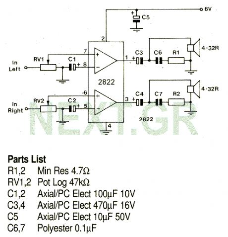
A stereo power amp designed for use in portable players and radios. A 3V supply can be used to drive headphones providing 20mW in 32 Ohms per channel.
Source: NEXT.GR (View)
View full Circuit Diagram | Comments | Reading(0)
Water Softener Circuit
Published:2012/9/13 20:53:00 Author:Ecco | Keyword: Water Softener
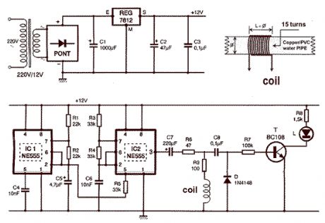
That circuit is based at a technique to remove or neutralize the salt in water, and protect the pipes at home as well as the washing machines or our selves from salt. Its called water softener and its automated circuit using two 555 timers.
Source: NEXT.GR (View)
View full Circuit Diagram | Comments | Reading(5775)
2 Watts FM transmitter
Published:2012/9/13 20:52:00 Author:Ecco | Keyword: 2 Watts, FM transmitter

This is a nice 2 Watts FM transmitter. It has a Super-Sensitive pre-amplification with BC109 and BC177 with more than 100% signal modulation. The job finish the 2N2219 by Motorola. For the Coils you should use 1mm wire(enameled), L1= 3 turns - 10mm diameter, L2= 1 turn - 10mm diameter. R9 trimmer controls the modulation gain. The tunning is easy by controlling C9 trimmer (88-108 MHz). The RFC J should be the VK220J with ferrite (VK200 is not suitable).
Source: NEXT.GR (View)
View full Circuit Diagram | Comments | Reading(2815)
50W Hi-Fi amplifier with TDA7294
Published:2012/9/13 20:51:00 Author:Ecco | Keyword: 50W, Hi-Fi amplifier

The TDA7294 is a Hi-Fi amplifier and can give 100W RMS but with 10% distortion. Supplying 30 Volts you can have 50 Watts RMS with 1% distortion. Frequency range start at 16Hz and can reach 100KHz. Make sure you are using good heatsink. The chip supports mute function as well.
Source: NEXT.GR (View)
View full Circuit Diagram | Comments | Reading(2503)
FM surveillance BuG Transmitter
Published:2012/9/13 20:50:00 Author:Ecco | Keyword: FM surveillance BuG , Transmitter
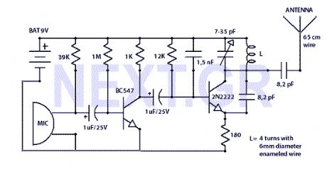
The Circuit shown can transmit voice to exceptionally good range. Tune trimmer to hear the signal to your near radio. Frequency range is 88-108 MHz. Max current consumption is 30mA. You can power the bug with a 9Volt Battery, or you can plug a power supply to feed in 9-12 Volts.
Source: NEXT.GR (View)
View full Circuit Diagram | Comments | Reading(2698)
TV and FM jammer schematic
Published:2012/9/13 20:45:00 Author:Ecco | Keyword: TV, FM jammer
The Jammer is a very small circuit and can fit inside a small plastic box with 9V battery inside. It can be very illegal if you attach an external antenna so don't. adjust frequency by turning trimmer.
Source: NEXT.GR (View)
View full Circuit Diagram | Comments | Reading(5042)
In-Car lights delay circuit
Published:2012/9/13 20:39:00 Author:Ecco | Keyword: In-Car lights, delay circuit

This circuit switch slowly on and off the internal lights in a car. The delaying time can be adjusted changing the values of the 10k, 4M7 resistors and capacitor.
Source: NEXT.GR (View)
View full Circuit Diagram | Comments | Reading(1853)
Amplifier input signal overdrive auto-protection
Published:2012/9/13 20:39:00 Author:Ecco | Keyword: Amplifier input, signal overdrive , auto-protection

That circuit protects the overdriven signals going into an amplifier. Instead of a zener diode we use a transistor. That way we ensure that the above the ordinary input voltages ( 1 volt r.m.s.) can be acheaved without distortion. Also the use of a transistor limits the number of components used in this schematic.
Source: NEXT.GR (View)
View full Circuit Diagram | Comments | Reading(1331)
Passive subwoofer filter
Published:2012/9/13 20:38:00 Author:Ecco | Keyword: Passive subwoofer, filter

The schematic shown, does no need any power supply because is a simple low frequency passive filter. It could be usefull if you want to drive an extra subwoofer from your stereo system.
Source: NEXT.GR (View)
View full Circuit Diagram | Comments | Reading(0)
| Pages:335/2234 At 20321322323324325326327328329330331332333334335336337338339340Under 20 |
Circuit Categories
power supply circuit
Amplifier Circuit
Basic Circuit
LED and Light Circuit
Sensor Circuit
Signal Processing
Electrical Equipment Circuit
Control Circuit
Remote Control Circuit
A/D-D/A Converter Circuit
Audio Circuit
Measuring and Test Circuit
Communication Circuit
Computer-Related Circuit
555 Circuit
Automotive Circuit
Repairing Circuit