
Circuit Diagram
Index 326
Smart Heater Controller
Published:2012/9/19 21:51:00 Author:Ecco | Keyword: Smart , Heater Controller

Minuscule circuit of the electronic heater controller presented here is built around the renowned 3-Pin Integrated Temperature Sensor LM35 (IC1) from NSC. Besides, a popular BiMos Op-amp CA3140 (IC2) is used to sense the status of the temperature sensor IC1, which also controls a solid-state switch formed by a high power Triac BT136(T1). Resistive type electric heater at the output of T1 turns to ON and to OFF states as instructed by the control circuit. This gadget can be used as an efficient and safe heater in living rooms, incubators, heavy electric/electronic instrument etc.Normally, when the temperature is below a set value (Decided by multi-turn preset pot P1), voltage at the inverting input (pin2) of IC1 is lower than the level at the non-inverting terminal (pin3). So, the comparator output (at pin 6) of IC1 goes high and T1 is triggered to supply mains power to the desired heater element.When the temperature increases above the set value, say 50-60 degree centigrade, the inverting pin of IC1 also goes above the non-inverting pin and hence the comparator output falls. This stops triggering of T1 preventing the mains supply from reaching the heater element. Forunately, the threshold value is user-controllable and can be set anywhere between 0 to 100 Degree centigrade.The circuit works off stable 9Volt dc supply, which may be derived from the mains supply using a standard ac mains adaptor (100mA at 9V) or using a traditional capacitive voltage divider assembly. You can find such power circuits elsewhere in this website.
Note:CA3140 (IC2) is highly sensitive to electrostatic discharge (ESD). Please follow proper IC Handling Procedures.
Electronic Heater Controller Circuit Schematic
?
2 Responses to “Smart Heater Controller”
Source: electroschematic.com
(View)
View full Circuit Diagram | Comments | Reading(1578)
Clear Glass Sensor
Published:2012/9/19 21:50:00 Author:Ecco | Keyword: Clear , Glass Sensor
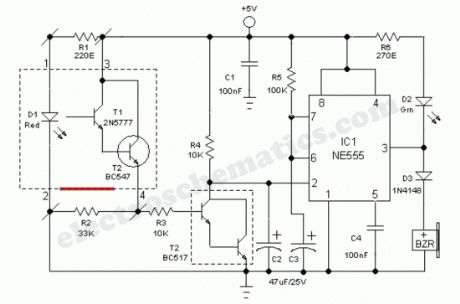
Industrial grade clear glass sensor modules are widely available but not within the reach of an average electronics hobbyist. The simple clear glass sensor circuit can be used for experiment/hobby purposes. The concept is very simple and is based on a home-made sensor unit comprising one high efficiency ultra bright red LED (D1) and a standard phototransistor 2N5777 (T1). The circuits works off a well regulated 5Volt dc supply.When power is turned to ON, light transmitter D1 starts emitting visible red color beam towards outside through a red colored filter glass. If a clear glass is placed in front of it,within 1-5 mm, light from D1 is not highly reflected. So T1 does not conduct and the monoshot wired around IC1 (NE555) is in standby state. This condition is indicated by the green LED (D2).However, in case of some (not all) unclear/colored/labelled glass material, reflected red light from it turn on the phototransistor T1 and IC1 is triggered by this action. Immediately D2 goes off and the piezobuzzer starts beeping for a short duration (near 5 secs with R5, C3 values shown). This acoustic sounder can be replaced with a 5V/600 Ohm relay to control external loads. Remember to add a freewheeling diode (like 1N4148) across the relay coil in antiparallel to suppress the counter emf generated during relay switching.
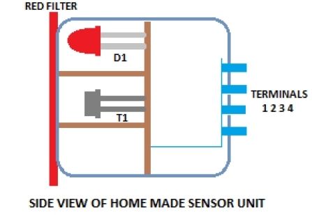
As stated, the home made sensor consists of an LED, phototransistor and a small piece of red filter glass. If properly aligned (see fig.2) a detection range of 5mm maximum can be expected. Alternatively, you can try a special reflective type opto-sensor (like CNY70) for this purpose. Finally, note that this is a basic design idea and thus, for optimum perfomance retouch the values of components R1, R2, R3, R4 and C2 using theoritical and empirical method.
(View)
View full Circuit Diagram | Comments | Reading(2473)
Low Current Flasher circuit
Published:2012/9/19 21:50:00 Author:Ecco | Keyword: Low Current , Flasher
This is a low current flasher consumes only a few Micro amperes current and lights a high bright LED day and night for more than one year. This can be used in switch boards, key stand etc to locate them easily. Unlike other LED flashers, it uses the current from the capacitor to light the LED. With a 9 volt battery, the LED flashes more than one year.
IC1 is designed as a simple oscillator using only one gate. The LED is placed in the discharge path of capacitor C1.Capacitor C1 charges through D1 and R1 and discharges through the LED and R2. Power consumoption depends on the values of R1 and C1. With higher values LED shows low brightness but power consumption will be less.
Low current Flasher Schematics
One Response to “Low Current Flasher circuit”
(View)
View full Circuit Diagram | Comments | Reading(1242)
IR Beam breaker circuit
Published:2012/9/19 21:49:00 Author:Ecco | Keyword: IR Beam , breaker
This is an Infrared beam breaking alarm ideal to use in entry or passages.It is based on the working of the popular IR sensor Module TSOP 1738 which senses 38 kHz Infrared pulses from the IR LED of the transmitter. Range of the circuit is about 5 meters if the transmitter and receiver are properly aligned
TSOP 1738 IR sensor module responds to only 38kHz pulsed infrared rays. It will not sense continuous IR ray from the IR LED.So a transmitter circuit(as one in TV remote handset) based on 555 IC is required. Any standard transmitter circuit based on 555 IC can be used. But its output should be 38kHz exactly.TSOP 1738 gives 5 volt output and 5mA current in the off position. That is when IR rays are not available.Its output is current sinking so that when it receives 38kHz IR rays, output becomes zero.Pin 2 of the module should get a supply voltage between 4.5 to 6 volts.Higher voltage above 6 volts will destroy the device. The module is generally immune to ambient light, but may responds to sources of noice such as electronic ballasts.
IR Beam breaker Schematics
Out put from the IR module is given to the inverting input of IC1. LM311 is a precision voltage comparator . It looks like the common Op Amps like LM741, CA3130,CA 3140,TL071 etc.But its pin connections and output are different from other Op Amps.Pin 2 Non invertingPin3 InvertingPin 1 GroundPin8 VccPin7 Current sinking Output
The non inverting input of IC1 is connected to a potential divider comprising R1 and R2. When the IR sensor gets IR pulses from the transmitter, output of IC1 remains high. When the IR beam breaks, output from the sensor becomes high which triggers IC1. It then sinks current to activate buzzer and LED.
3 Responses to “IR Beam breaker circuit”
Source: electroschematic.com
(View)
View full Circuit Diagram | Comments | Reading(1212)
Warning Alarm circuit with CD4001
Published:2012/9/19 21:49:00 Author:Ecco | Keyword: Warning Alarm

Unorthodox warning alarm circuit presented here is infact a single chip based general purpose sounder, which produces a pulsed alert tone when its input receives a valid trigger signal. The circuit can be easily interfaced with a number of electronic gadgets and sensors and it requires only 12V dc supply input for proper working. A positive level input at trigger point (J1) activates the warning alarm unit.At the heart of the circuit is a popular quad – two input NOR gate IC CD4001, here wired as two independent gated astable multivibrators. Initially, in standby mode, T1 is off and the tone generators are inactive. When T1 is enabled by a proper +ve level trigger signal, pin 1 of CD4001 is pulled low through switching diode D1 first astable block enters in active mode and then activates the second astable block, which is configured as an acoustic alarm. A large piezo-ceramic element (acoustic transducer) at the output of (pin 11) CD4001 will give superb results.
Warning Alarm Circuit Schematic
?
3 Responses to “Warning Alarm circuit with CD4001”
Source: electroschematic.com
(View)
View full Circuit Diagram | Comments | Reading(1191)
Wind Sound Effects circuit
Published:2012/9/19 21:43:00 Author:Ecco | Keyword: Wind Sound Effects

This wind sound effect generator circuit perfectly imitate the noise of the wind. Transistor T1 is connected as a Zener diode and will provide a noise signal to T2. The amplified signal by T2 is led to a frequency selective amplifier built with 741. With potentiometers P2a/P2b/P2c you can adjust the middle frequency of the filter and the wind sound. P1 adjusts the intensity of the sound which imitates the wind: an international scale Beaufort of wind intensity will make the adjustment easier.For P2 you may use a quadruple potentiometer of 15KΩ or 2 pots connected in parallel (P2c). If it is necessary the adjustment of the double T filter may be done for another value of P2. For that you need this formula:f = 1/2*pi*R*C with R=P2a=P2b=P2c and C=C5/2=C6=C7P2 may be simulated from many trimmer potentiometers (for vertical mounting of the plate).
Wind Effects Generator Circuit Schematic
?
One Response to “Wind Sound Effects circuit”
Source: electroschematic.com
(View)
View full Circuit Diagram | Comments | Reading(1028)
Rain Sound Effects Generator circuit
Published:2012/9/19 21:43:00 Author:Ecco | Keyword: Rain Sound Effects , Generator

This rain sound effects generator circuit simulates the rain noise and may be used in the field of electronic music and radio shows. As a noise source we use a germanium diode that is directly polarized then is amplifier by a single stage amplifier in order to obtain an acceptable audio level.A high-pass filter with an adjustable lower limit, built with P1 and C3, allow coverage of the entire range of sound effects from light rain and to torrential rain.The current consumption is low so you can use a 9V battery. Instead of BC107 you can use any NPN transistor.
Rain Sound Effects Circuit Schematic
?
10 Responses to “Rain Sound Effects Generator circuit”
Source: electroschematic.com
(View)
View full Circuit Diagram | Comments | Reading(1904)
Cheap Metal Detector circuit
Published:2012/9/19 21:42:00 Author:Ecco | Keyword: Cheap , Metal Detector
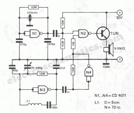
The working principle of this cheap and easy to build metal detector circuit consists in mixing two equal frequencies which causes a low-frequency interference. When one of the oscillators become unstable then the frenquency of the interference will be modified. The metal detector circuit is built with CD4011. The oscillator is built with NAND N1 and a ceramic filter of intermediary freq. (470kHz). The second oscillator is with N3 and a LC combination. The freq. of this osc. is adjusted in such way that will produce an audible oscillation of both freqs.Thru N4, the signal from the variable osc. is amplified. If the sensor coil L1 is closer to a metal object then it will modify the auto-induction of the coil, the osc. is unbalanced and the sound will modify.The metal detector’s coil is made of: 70 turns of enamelled copper with diam. of 0.3-0.6 mm on a 5 cm diam.
Easy to build metal detector schematic
?
4 Responses to “Cheap Metal Detector circuit”
Source: electroschematic.com
(View)
View full Circuit Diagram | Comments | Reading(1346)
Smart Cooling Fan Circuit
Published:2012/9/19 21:41:00 Author:Ecco | Keyword: Smart , Cooling Fan
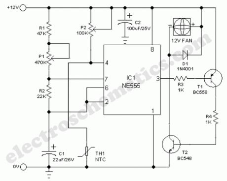
A continuously running cooling fan is a big nuisance and is not very crucial in most instruments. The 12V smart fan control presented here allows the fan to run at rates varying from once a second to once in ten seconds approximately. In case of a battery powered instrument, this idea will save some power too!Basically, the cooling fan circuit is an astable multivibrator built around NE555(IC1), in which the output level at pin 3 remains high for a long time and low for a short time. The low level output at pin 3 drives the cooling fan via T1 and T2. This timeout (delay) period can be adjusted using preset pot P1.A simple temperature detector mechanism is deliberately added to the main circuit. Here, a negative temperature coefficient (NTC) type thermistor (TH1) functions as the heat monitor. Normally the resistance of TH1 is high and the astable is enabled through trimpot P2. When temperature increases beyond a limit set by preset pot P2, the astable is disabled by the grounding of its reset terminal (pin4) via TH1. At this time, output at pin 3 of IC1 remains in low level and the cooling fan sweeps continuously.
Temperature dependent cooling fan schematic
?
11 Responses to “Smart Cooling Fan Circuit”
Source: electroschematic.com
(View)
View full Circuit Diagram | Comments | Reading(2334)
Step Alarm Circuit
Published:2012/9/19 21:41:00 Author:Ecco | Keyword: Step Alarm
This Circuit can monitor the door steps or Staircase. When a person crosses the steps, the alarm sounds indicating the entry. The circuit is too sensitive and operates in day light.The circuit uses an NPN Darlington phototransistor L14F1. It senses the intensity of light through its exposed base and passes current in the collector- emitter path. When there is light, the phototransistor conducts and C1 charges up to its full voltage level. The alarm circuit uses a Monostable timer built around IC NE555. The triggering threshold of IC1 is adjusted using VR1. So normally the trigger pin 2 of IC1 remains high as set by VR1. When the shadow of the moving person masks the phototransistor, it turns off allowing C1 to discharge through R1. This momentarily makes the trigger pin 2 of IC1 low and the timing cycle starts. With the given values of R2 and C2, Buzzer sounds for two minutes.
Step Alarm Circuit
SettingThe circuit can be constructed on a small piece of Perf board. The circuit is designed to operate in day light. Switch off the circuit in the evening to avoid false alarm. If a lamp is provided opposite to the phototransistor on the opposite wall of staircase, the circuit can be used as day and night alarm. Align the lamp in the line – of – sight of Phototransistor. Adjust VR1 till the circuit becomes silent.?
8 Responses to “Step Alarm Circuit”
Source: electroschematic.com
(View)
View full Circuit Diagram | Comments | Reading(775)
12 V Gelled-Electrolyte Battery Charger
Published:2012/9/19 21:39:00 Author:Ecco | Keyword: 12 V, Gelled-Electrolyte, Battery Charger

This circuit is a high-performance charger for gelled-electrolyte lead-acid batteries. This charger quickly recharges the battery and shuts off at full charge. It uses the well-known LM301A and LM350 ICs.Initially, charging current is limited to 2A. As the battery voltage rises, current to the battery decreases, and the current had decreased to 150 mA, the charge switches to a lower float voltage which prevents overcharge.When the start switch is pushed, the output of the charger goes to 14.5V. As the battery approaches full charge, the charging current decreases and the output voltage is reduced to 14.5V to about 12.5V, terminating the charging. Transistor then lights the LED as a visual indicator of full charge.
12V battery charger circuit schematic
?
One Response to “12 V Gelled-Electrolyte Battery Charger”
Source: electroschematic.com
(View)
View full Circuit Diagram | Comments | Reading(2537)
Wind powered battery charger
Published:2012/9/19 21:38:00 Author:Ecco | Keyword: Wind , powered, battery charger

In this wind powered battery charger circuit the dc motor is used as a generator. The voltage output is proportional to its rpm. The LTC1042 monitors the voltage output and provides the following control function.1. if the voltage output is below 13.8V, the control circuit is active and the NiCad battery is charging through the LM334 current source. The lead-acid battery is not being charged.2. if the voltage output is between 13.8V and 15.1V, the 12V lead-acid battery is being charged at about 1-amp/hour rate (limited by the power FET).3. if generator voltage exceeds 15.1V (a condition caused by excessive wind speed or when the 12V battery is fully charged), the a fixed load is connected, which limits the generator rpm to prevent damage.This wind powered charger can be used as a remote source of power where wind energy is plentiful, such as on sailboats or at remote radio repeater sites. Unlike solar-powered panels, this system will function in bad weather and at night.
Battery Charger Schematic using wind energy
7 Responses to “Wind powered battery charger”
Source: electroschematic.com
(View)
View full Circuit Diagram | Comments | Reading(0)
LED Searchlight Circuit
Published:2012/9/19 21:38:00 Author:Ecco | Keyword: LED Searchlight
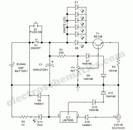
This LED searchlight comprises a sealed maintenance-free (SMF) battery, constant voltage battery charger, six high efficiency white LEDs and a LED light level control circuit.White LEDs (D1-D6) gets power supply from the 6V battery through on/off switch S1 (Switch S2 can be used for momentary power switching). Transistor T1 and associated components forms a light level control circuit. With the help of the linear potmeter (P1), user can adjust the intensity of the LED light output.
The search light can be recharged by connecting an external ac mains adaptor (12V/1A) to its charger input (J1). Internal battery charger circuit is built around the popular three pin fixed regulator LM7806(IC1). Red LED (D11) works as a charge mode indicator.
LED Searchlight Circuit Schematic
?
One Response to “LED Searchlight Circuit”
Source: electroschematic.com (View)
View full Circuit Diagram | Comments | Reading(1740)
DIY Digital Thermometer Circuit
Published:2012/9/19 21:38:00 Author:Ecco | Keyword: DIY, Digital Thermometer

This diy digital thermometer circuit can measure temperatures up to 150°C with an accuracy of ±1°C. The temperature is read on a 1V full scale-deflection (FSD) moving-coil voltmeter or digital voltmeter.How the digital thermometer worksOperational amplifier IC 741 (IC3) provides a constant flow of current through the base-emitter junction of npn transistor BC108 (T1). The voltage across the base-emitter junction of the transistor is proportional to its temperature. The transistor used this way makes a low-cost sensor. You can use silicon diode instead of transistor.The small variation in voltage across the base-emitter junction is amplified by second operational amplifier (IC4), before the temperature is displayed on the meter. Preset VR1 is used to set the zero-reading on the meter and preset VR2 is used to set the range of temperature measurement.Operational amplifiers IC3 and IC4 operate off regulated ±5V power supply, which is derived from 3-terminal positive voltage regulator IC 7805 (IC1) and negative low-dropout regulator IC 7660 (IC2). The entire circuit works off a 9V battery.Assemble the circuit on a general-purpose PCB and enclose in a small plastic box. Calibrate the thermometer using presets VR1 and VR2. After calibration, keep the box in the vicinity of the object whose temperature isto be measured.
Sent by Mihail Dorutz, CH. Thanks a lot!
Digital Thermometer Circuit Schematic
5 Responses to “DIY Digital Thermometer Circuit”
Source: electroschematic.com
(View)
View full Circuit Diagram | Comments | Reading(1393)
NiMH Battery Charger circuit
Published:2012/9/19 21:37:00 Author:Ecco | Keyword: NiMH, Battery Charger
Here is a simple battery charger for the Nickel Metal Hydride battery that requires current regulated charging. The charger provides 140 mA current for quick charging of the battery.
Power supply section consists of a 0-18 volt AC 1 Ampere step-down transformer, a full wave bridge rectifier comprising D1 through D4 and the smoothing capacitor C1. Current regulation is achieved by the action of R1,R2 and the Epitaxial Darlington PNP transistor TIP 127. Resistor R1 keeps the charging current to 140 milli amperes. LED and resistor R2 plays an important role to control the base current of T1 and thus its output.
NiMH Battery Charger Circuit
Around 2.6 volts drop develops across the LED which appears at the base of T1. Emitter – base junction of T1 drops around 1.2 volts. So 2.6 – 1.2 volts gives 1.40 volts. So the current passing through R1 will be 1.40 V / 10 = 0.14 Amps or 140 Milli Amps. The LED act as the charging status indicator. LED lights only if the battery is connected to the output of circuit and the input voltage is normal.
2 Responses to “NiMH Battery Charger circuit”
Source: electroschematic.com
(View)
View full Circuit Diagram | Comments | Reading(2206)
Dew Detector Probe Circuit
Published:2012/9/19 21:27:00 Author:Ecco | Keyword: Dew Detector, Probe
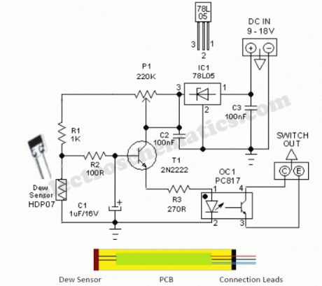
This simple and economical Dew Detector Probe circuit works on 5V dc supply. It is useful for checking the presence of dew (condensed moisture) inside sensitive electronic devices like VTR, Camera,C opier,Computer etc. The circuit utilises a ready-made dew sensor element HDP-07 (from “Hokuriku”). However, you can use any other type (carefully lifted from a discarded VTR or similar equipment) without any circuit modification.The principle of the ready made dew sensor element is based on the change in resistance of a conductive polymer in a thin film on a small ceramic substrate. As the sensing polymer wet (90 to 95% Relative Humidity), its resistance will increase drastically because the polymer expands and therefore causes a larger distance between the conductive particles. After successful construction, enclose the whole unit in a small aluminium tube as shown in the figure.This circuit has an on-board voltage regulator wired around LM78L05 (IC1). Although we can safely feed dc supply upto +35 V to this circuit, dc input in +9 to 12 V range is recommended. Similarly an opto-coupler PC817 (OC1) is used to isolate the detector circuit from the rest of the external switch/control unit. As you may noticed, this is an open-collector output which can be easily interfaced to any analogue or digital switch/control circuits like relay switches,alarm units etc.In idle state resistance of the dew sensor element is very low and thus most of the base current of transistor T1 (2N2222) finds an alternative path via dew sensor and T1 remains in cut off. Condition. When Relative Humidity (RH) exceeds and touches the 90-95% level, dew sensor element behaves almost like an open component (very high resistance), T1 is forward biased and the opto-coupler is energised. Note that the adjustment of threshold set preset pot P1 is very critical. Use theoritical & empirical methods to calibrate the detection mechanism.
Dew Sensor Circuit Schematic
Source: electroschematic.com (View)
View full Circuit Diagram | Comments | Reading(1646)
Portable Solar Power Inverter
Published:2012/9/19 21:26:00 Author:Ecco | Keyword: Portable, Solar, Power Inverter

A compact and portable 12V Solar power inverter circuit that will keep away darkness. This tried and tested design converts 12V DC from the storage battery of any solar power system to 230V AC that is enough to power a number of energy saving CFLs. Just feed 12V DC input through input jack J1 (with right polarity) and flip switch S1 to ON position!The 12V power inverter circuit, optimised for CFL loads, uses IC CD4047B (IC1) as a freerunning astable oscillator. Capacitor C2 and resistor R2 are timing components. The pulse repetition rate of IC1 is determined by the value of 4.4xC2xR2. IC1 generates cmplementary squarewave signals at its output pins 10 and 11. Power Mosfets T1 and T2 serve as drivers for the high-voltage generator,realised using step-up transformer (X1).Note that an ordinary (AC 230V to 12-0-12/5Amp) step-down transformer is here used for reverse function (step-up) and its output is available at AC mains outlet J2. You can light up two to four low wattage (ie 11W at AC 230V) ready-made Compact Flourescent Lamps (CFLs) using this circuit. Two small, independent heatsinks are necessary for T1 and T2. Finally, you can try an AC 230V to 9-0-9/5Amp rated transformer as X1.
12V Power Inverter Circuit Schematic
?
34 Responses to “Portable Solar Power Inverter”
Source: electroschematic.com
(View)
View full Circuit Diagram | Comments | Reading(1864)
Light Operated Relay circuit
Published:2012/9/19 21:26:00 Author:Ecco | Keyword: Light Operated, Relay
This Light Sensitive Circuit can operate a Relay to switch on Lamps or any AC loads when it senses darkness. It is ideal to use as switch less Night lamps driver.
LDR is used as the light sensor. Its resistance is low about 100 ohms in bright light but increases to 10 meg or more in dark. Preset VR1 set the sensitivity of the LDR. During day time LDR conducts so that the gate of T1 will not get base bias. So that relay remains de energized. When the intensity of light reduces, LDR offers more resistance and more current passes to the base of T1 and it conducts. Relay then switch on the load. Adjust VR1 to trigger relay at the particular light level. LED indicates the activation of relay.
Light Operated Relay Circuit
?
8 Responses to “Light Operated Relay circuit”
Source: electroschematic.com
(View)
View full Circuit Diagram | Comments | Reading(1096)
Ornamental LED circuit
Published:2012/9/19 21:25:00 Author:Ecco | Keyword: Ornamental LED
Here is a simple LED flasher for decoration purpose. The High bright LEDs flashes alternately giving a brilliant colour display. The circuit is a simple Astable multivibrator using two NPN transistors T1 and T2.The circuit works on the principle of charging and discharging of capacitors C1 and C2. Current from the positive of battery flows through first set of LEDs D1-D5 to the collector of T1 through resistor R1.Resistor R1 limits current through the LEDs to protect them. The current through R1 and LEDs charge capacitor C1. It then discharges through the base of T2 and resistor R4. This gives base current to T2 and it conducts. As a result second set of LEDs D6-D10 lights.As the Capacitor C1 discharges completely, T2 turns off. LEDs D6-D10 also turns off.
The same thing happens in the other side also. This gives alternate flashing of LEDs.Thus the flashing effect is produced through the switching of T1 and T2 by the charge from capacitors.Flashing rate can be changed by changing the value of R3,R4 or C1,C2. If 500K preset is used in the place of R3/R4, flashing rate can be varied.
Ornamental LED Circuit
Source: electroschematic.com (View)
View full Circuit Diagram | Comments | Reading(1223)
Multi pattern Lamps
Published:2012/9/19 21:25:00 Author:Ecco | Keyword: Multi pattern Lamps
Multipattern serial lamps are now available at very low cost. These china make serial lamps circuit gives 8 pattern lighting like Combination, In Wave, Sequential, SLO-GLO, Chasing / Flashing, Slow-Fade, Twinkle/Flash, Steady On patterns etc. The same circuit can be used to drive four 40-60 Watts AC bulbs to decorate X mas stars.
The circuit is directly connected to AC lines. The PCB has a COB( Chip On Board) with a programmed ROM chip that generates multi patterns. The patterns can be automatic or can be selected through a push switch. The same chip can directly drive four 40-60 watts bulbs to decorate the Xmas stars. All the eight patterns will be generated in the bulbs giving an elegant display.
Multipattern Lamps Circuit
How to connect1.Open the circuit board box and remove the PCB.
2. There will be 5 wires on one side and 2 wires on the opposite side of PCB.
3. The 2 wires are for AC lines (Phase and Neutral). This can be used either way round.
4. Out of the 5 wires on the other side, 4 wires are for lamps and the last one for Neutral.
5. Remove the wires and solder 4 colored wires for lamps and a green / black wirefor neutral.
6. Connect 2 Red wires for Phase and Neutral.
7. Solder 2 wires at the contacts of the switch soldered in the PCB and connectthe wires to a Push-to-On switch to select patterns.
8. Enclose the wired PCB in a shock proof case and connect the Lamps as shown inthe diagram.
9. Connect an AC plug to the wires for Phase and Neutral.
10. Do not use bulbs above 60 watts.
Caution: The circuit is extremely dangerous since its PCB is at mains lethal potential. Do not try the circuit if you are not experienced in handling 230 volt AC. Connect the circuit to AC lines only after enclosing it in a shock proof case. Do not touch or trouble shoot when the PCB is in the open condition.
Author and Electroschematics.com will not have any responsibility to causality, if the circuit is mishandled.?
One Response to “Multi pattern Lamps”
Source: electroschematic.com
(View)
View full Circuit Diagram | Comments | Reading(1111)
| Pages:326/2234 At 20321322323324325326327328329330331332333334335336337338339340Under 20 |
Circuit Categories
power supply circuit
Amplifier Circuit
Basic Circuit
LED and Light Circuit
Sensor Circuit
Signal Processing
Electrical Equipment Circuit
Control Circuit
Remote Control Circuit
A/D-D/A Converter Circuit
Audio Circuit
Measuring and Test Circuit
Communication Circuit
Computer-Related Circuit
555 Circuit
Automotive Circuit
Repairing Circuit