Sensor Circuit
Clear Glass Sensor
Published:2012/9/19 21:50:00 Author:Ecco | Keyword: Clear , Glass Sensor | From:SeekIC


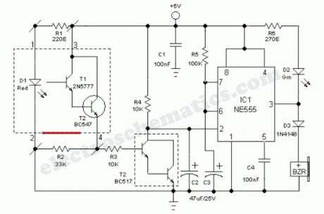
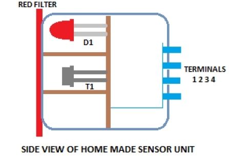
Industrial grade clear glass sensor modules are widely available but not within the reach of an average electronics hobbyist. The simple clear glass sensor circuit can be used for experiment/hobby purposes. The concept is very simple and is based on a home-made sensor unit comprising one high efficiency ultra bright red LED (D1) and a standard phototransistor 2N5777 (T1). The circuits works off a well regulated 5Volt dc supply.When power is turned to ON, light transmitter D1 starts emitting visible red color beam towards outside through a red colored filter glass. If a clear glass is placed in front of it,within 1-5 mm, light from D1 is not highly reflected. So T1 does not conduct and the monoshot wired around IC1 (NE555) is in standby state. This condition is indicated by the green LED (D2).However, in case of some (not all) unclear/colored/labelled glass material, reflected red light from it turn on the phototransistor T1 and IC1 is triggered by this action. Immediately D2 goes off and the piezobuzzer starts beeping for a short duration (near 5 secs with R5, C3 values shown). This acoustic sounder can be replaced with a 5V/600 Ohm relay to control external loads. Remember to add a freewheeling diode (like 1N4148) across the relay coil in antiparallel to suppress the counter emf generated during relay switching.
As stated, the home made sensor consists of an LED, phototransistor and a small piece of red filter glass. If properly aligned (see fig.2) a detection range of 5mm maximum can be expected. Alternatively, you can try a special reflective type opto-sensor (like CNY70) for this purpose. Finally, note that this is a basic design idea and thus, for optimum perfomance retouch the values of components R1, R2, R3, R4 and C2 using theoritical and empirical method.
Reprinted Url Of This Article:
http://www.seekic.com/circuit_diagram/Sensor_Circuit/Clear_Glass_Sensor.html
Print this Page | Comments | Reading(3)

Article Categories
power supply circuit
Amplifier Circuit
Basic Circuit
LED and Light Circuit
Sensor Circuit
Signal Processing
Electrical Equipment Circuit
Control Circuit
Remote Control Circuit
A/D-D/A Converter Circuit
Audio Circuit
Measuring and Test Circuit
Communication Circuit
Computer-Related Circuit
555 Circuit
Automotive Circuit
Repairing Circuit
Code: