Electrical Equipment Circuit
Smart Cooling Fan Circuit
Published:2012/9/19 21:41:00 Author:Ecco | Keyword: Smart , Cooling Fan | From:SeekIC

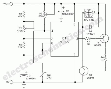
A continuously running cooling fan is a big nuisance and is not very crucial in most instruments. The 12V smart fan control presented here allows the fan to run at rates varying from once a second to once in ten seconds approximately. In case of a battery powered instrument, this idea will save some power too!Basically, the cooling fan circuit is an astable multivibrator built around NE555(IC1), in which the output level at pin 3 remains high for a long time and low for a short time. The low level output at pin 3 drives the cooling fan via T1 and T2. This timeout (delay) period can be adjusted using preset pot P1.A simple temperature detector mechanism is deliberately added to the main circuit. Here, a negative temperature coefficient (NTC) type thermistor (TH1) functions as the heat monitor. Normally the resistance of TH1 is high and the astable is enabled through trimpot P2. When temperature increases beyond a limit set by preset pot P2, the astable is disabled by the grounding of its reset terminal (pin4) via TH1. At this time, output at pin 3 of IC1 remains in low level and the cooling fan sweeps continuously.
Temperature dependent cooling fan schematic
?
11 Responses to “Smart Cooling Fan Circuit”
Source: electroschematic.com
Reprinted Url Of This Article:
http://www.seekic.com/circuit_diagram/Electrical_Equipment_Circuit/Smart_Cooling_Fan_Circuit.html
Print this Page | Comments | Reading(3)

Article Categories
power supply circuit
Amplifier Circuit
Basic Circuit
LED and Light Circuit
Sensor Circuit
Signal Processing
Electrical Equipment Circuit
Control Circuit
Remote Control Circuit
A/D-D/A Converter Circuit
Audio Circuit
Measuring and Test Circuit
Communication Circuit
Computer-Related Circuit
555 Circuit
Automotive Circuit
Repairing Circuit
Code: