
Circuit Diagram
Index 339
Automatic series reactance starting three-phase motor 1
Published:2012/9/12 2:03:00 Author:Ecco | Keyword: Automatic series, reactance starting, three-phase motor
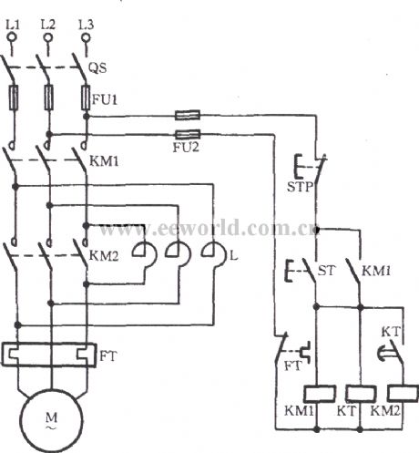
As shown in the diagram, thecircuituses time relay KTto realizeautomatic shorting reactor without pressing operation buttonby handsin the switching process of startup and operation.
(View)
View full Circuit Diagram | Comments | Reading(2227)
The directly start circuit by change-over switch
Published:2012/9/11 22:37:00 Author:Ecco | Keyword: directly start , change-over switch
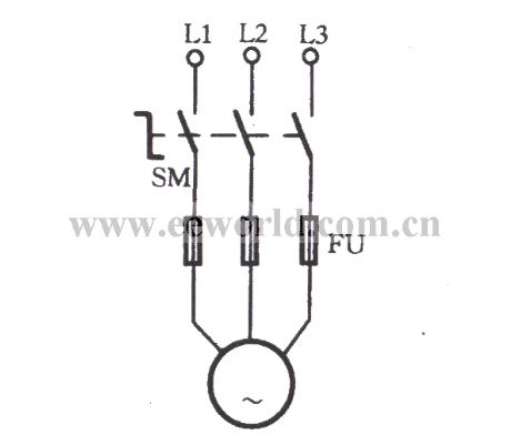
As shown in the diagram, SM is a change-over switch which is also known as combination switch, and the common models inlcudeHZ10, HZ15 series. It has a rotary handleto drive three movable contact pieces rotating at the same time and turn ON or OFF respectively the three pairs of stationary contact pieces.When it isturned on, the motor starts rotating; when it is cut off, the motor M stopsrotating. The circuit isused for the grinders, lathes and other mechanical equipments.
(View)
View full Circuit Diagram | Comments | Reading(1218)
Open-phase protection circuit using three current transformers
Published:2012/9/12 2:14:00 Author:Ecco | Keyword: Open-phase protection , three current transformers

As shown in figure, 1TA, 2TA and3TAin circuit are three current transformers, andtheir secondary circuit are connetcedin parallel, then the loop is connected to a current relay KA. Duringthe motor M is in normal operation, KA does not operate. When there is a phase failure, zero-sequence current is approximately 1.73 times ofthe rated current, then KA acts tocut off the power for motor.
(View)
View full Circuit Diagram | Comments | Reading(2688)
Voice-activated music outlet circuit using NJM2072D
Published:2012/9/12 2:16:00 Author:Ecco | Keyword: Voice-activated , music outlet

Asshown in the figure,the circuitusesvoice-activated ASICNJM2072D as the core component,butthe on-off ofoutletXS1 is controlled by TRIAC, and vocal circuit uses imitating animal soundIC KD- 56020 which is triggered bynegative level.
(View)
View full Circuit Diagram | Comments | Reading(962)
Voice-activated music outlet circuit 1 using NJM2072D
Published:2012/9/12 2:26:00 Author:Ecco | Keyword: Voice-activated , music outlet


As shown in the diagram, the circuit consists of acoustic sensor, voice integrated circuit, relay control circuit, songs sound circuit and AC buck rectifier circuit and other components, and it can be used for the voice control automatic lights, voice control musical fountain, voice control barricades indicator and voice-activated automatic doors. ICl use voice control ASIC NJM2072D which is the core of the circuit device, and its internal functional block diagram is shown in the following figure.
(View)
View full Circuit Diagram | Comments | Reading(1894)
Voice-activated music outlet circuit 2 using NJM2072D
Published:2012/9/11 22:26:00 Author:Ecco | Keyword: Voice-activated, music outlet

Asshown in the figure, it usesvoice-activated ASICNJM2072D as the core component,butthe on-off ofoutletXS1 is controlled by TRIAC, and vocal circuit uses imitating animal soundIC KD- 56020 which is triggered bynegative level.
(View)
View full Circuit Diagram | Comments | Reading(822)
Voice-activated music outlet circuit using SK-Ⅱ
Published:2012/9/12 2:28:00 Author:Ecco | Keyword: Voice-activated , music outlet

Asshown in the figure,the circuitincludes acoustic sensor , SK - II sound control circuit, relay control circuit, music sound circuit and AC buck rectifier circuit. BM is the acoustical / electrical transducer.
(View)
View full Circuit Diagram | Comments | Reading(580)
Voice-activated music outlet circuit using SL518
Published:2012/9/11 22:10:00 Author:Ecco | Keyword: Voice-activated, music outlet

Asshown in the figure, it usesvoice-activated ASICSL518 as the core component. SL518is animproved product on the basis of SL517 withfewer external components, and its output isemitteroutput with stronger drive ability.
(View)
View full Circuit Diagram | Comments | Reading(716)
Multifunctional fan control circuit using DZS-01
Published:2012/9/11 22:21:00 Author:Ecco | Keyword: Multifunctional fan, control

As shown in the circuit, the circuit uses fan control ASIC DZS-01 as the core component, whenthe fan is turned on,it isalso accompanied by beautiful harmonies of nature to give the joy of beauty for people.
(View)
View full Circuit Diagram | Comments | Reading(758)
The series connecting control circuit of electric contact pressure gauge and time relay
Published:2012/9/11 22:04:00 Author:Ecco | Keyword: series connecting , control , electric contact, pressure gauge , time relay

As shown in Figure, the circuit usestwo time relays KT1 , KT2 to connect with thecontactsofelectric contact pressure gauge SP in series. When liquid or gas pressure has not yet reached, it can overcome thetrembling or spark phenomenons because of the SP's incomplete separating andtoucing in the crash time of motor automatic start or stop,and itimprovesthe reliability of circuit.
(View)
View full Circuit Diagram | Comments | Reading(1983)
12-24V Impulse control dimmer
Published:2012/9/11 21:33:00 Author:Ecco | Keyword: 12-24V , Impulse control , dimmer

This circuit is intended for use with motors, lamps,heatings etc. Continuously from nearly zero up to maximum capacity (5-95%). Almost lossfree control by means of this impulse control. Nearly total turning moment of motors. The transistior T3 must absolutely be fastened on a heatsink with minimum dimentions of approximate 100x100x5mm. The heatsink has to be fixed insulated as the transistor has a conductive connection between the C-connection and the metal rear side. (View)
View full Circuit Diagram | Comments | Reading(1253)
Auto-Arming Car Alarm circuit
Published:2012/9/11 21:32:00 Author:Ecco | Keyword: Auto-Arming, Car Alarm

The car alarm here is a simple circuit with basic characteristics that cover all entrances at the car that has switches (doors etc).With one switch (arm-switch) the circuit waits for the sensor-switches to open and to activate it. So the horn with 1 sec pulses will sound imediatelly seconds so the driver can enter in car and disactivate the arming switch. (View)
View full Circuit Diagram | Comments | Reading(1504)
Offset controlled stereo amplifier circuit
Published:2012/9/11 21:31:00 Author:Ecco | Keyword: Offset , controlled , stereo amplifier

This stereo amplifier use the NE5517/A and has an excellent tracking of 0.3 dB typical easy. With the potentiometer, Rp, the offset can be adjusted. For AC-coupled amplifiers, the knob can be replaced by two resistors 5.1 k ohm. (View)
View full Circuit Diagram | Comments | Reading(1712)
Small leakage pre-amplifier
Published:2012/9/11 21:30:00 Author:Ecco | Keyword: Small leakage, pre-amplifier
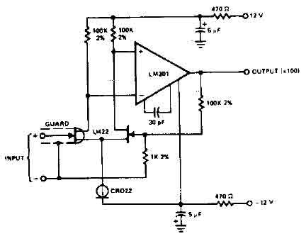
The circuit uses the LM301 has an input leakage of only 2 pA typical at 75 ° C and is used with 1 M ohm input resistance. The operating voltage has to be +-12V. (View)
View full Circuit Diagram | Comments | Reading(0)
Car alarm circuit using 555 timer
Published:2012/9/11 21:29:00 Author:Ecco | Keyword: Car alarm , 555 timer

555 timer produces a guaranteed delay, allowing the driver to deactivate the alarm and the elimination of a control switch vulnerable outside. (View)
View full Circuit Diagram | Comments | Reading(2078)
House Alarm Loop Circuit
Published:2012/9/11 21:29:00 Author:Ecco | Keyword: House Alarm , Loop

This circuit offers open and closed loop contacts (switches 1,2,3) that triggers the alarm ON and stays ON for 5 -10 minutes. The trigering delay (entrance/exit) is 27 seconds. This simple alarm circuit Has also a cancel button for reseting the circuit to stand-by mode again. (View)
View full Circuit Diagram | Comments | Reading(1854)
Car Alarm Security Circuit
Published:2012/9/11 21:28:00 Author:Ecco | Keyword: Car Alarm , Security

This car alarm circuit offers 18 seconds delay for the entrance and the exit. It sound continually for 6 minutes and automaticaly turns horn off and gets ready for the next trigering. (View)
View full Circuit Diagram | Comments | Reading(1201)
Simple House Alarm circuit
Published:2012/9/11 21:28:00 Author:Ecco | Keyword: Simple , House Alarm

This house alarm circuit has open and closed loop sensor and has self shutdown function. The delay after trigering can be adjusted from 1 minute to 12. The delay before trigering is 13 seconds. Offcourse all this timmings can be change with litle changes to few passive parts. (View)
View full Circuit Diagram | Comments | Reading(1134)
Clever Car alarm circuit
Published:2012/9/11 21:28:00 Author:Ecco | Keyword: Clever , Car alarm

When this car alarm circuit is activated it stays activated for 80 seconds. It has 15 seconds delay for the driver to enter and deactivate. and All timmings can be altered easilly. (View)
View full Circuit Diagram | Comments | Reading(1210)
CMOS inverters linear amplifier circuit
Published:2012/9/11 21:26:00 Author:Ecco | Keyword: CMOS inverter, linear amplifier

CMOS inverters can be used as linear amplifiers where negative feedback is applied. Best linearity is achieved with feedback applied around three inverters which gives almost perfect linearity up to a dynamic output of 5 V peak to peak with a 10 V supply rail The gain is set by the ratio of Rl and R2 and the values are typical for a gain of 100. The high frequency response with the values given is almost flat to 20 kHz. The frequency response is determined by Cl and C2. (View)
View full Circuit Diagram | Comments | Reading(1866)
| Pages:339/2234 At 20321322323324325326327328329330331332333334335336337338339340Under 20 |
Circuit Categories
power supply circuit
Amplifier Circuit
Basic Circuit
LED and Light Circuit
Sensor Circuit
Signal Processing
Electrical Equipment Circuit
Control Circuit
Remote Control Circuit
A/D-D/A Converter Circuit
Audio Circuit
Measuring and Test Circuit
Communication Circuit
Computer-Related Circuit
555 Circuit
Automotive Circuit
Repairing Circuit