
Circuit Diagram
Index 327
Light Sensor Circuit
Published:2012/9/19 21:24:00 Author:Ecco | Keyword: Light Sensor
This Circuit can compare the Light level in an area. It uses a PN Photodiode as the light sensor and IC CA3140 as voltage comparator. The circuit is ideal as the front end of burglar alarm circuits.The circuit uses an Op Amp as voltage comparator. In voltage comparator mode, the OpAmp compares the voltage levels between its inverting input (pin2) and the non- inverting input(pin3) and gives an appropriate high / low output. Generally in voltage comparator mode, voltage at one input is kept fixed using a Zener diode or a potential divider resistor chain. In the circuit, the voltage at pin 3 is set by VR1 so as to keep the output high in a particular light level. The high output keeps the LED off. The PN Photodiode act as the light sensor. When the light reduces, current through the photodiode decreases. This increases the voltage at pin 2 of comparator and the output swings to low state. Current then flows through R2 and LED into the comparator and LED lights. This indicates, low light level or darkness.
Light Sensor Circuit
?
4 Responses to “Light Sensor Circuit”
Source: electroschematic.com (View)
View full Circuit Diagram | Comments | Reading(1606)
DIY Solar Birdhouse Light
Published:2012/9/19 21:24:00 Author:Ecco | Keyword: DIY, Solar Birdhouse Light
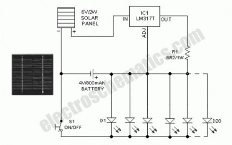
This solar birdhouse light is an economical circuit of a mini solar lighting system circuit is presented here. At the heart of the circuit is a mini 6V/2W solar panel. Here, this solar panel is used to charge a 4V/800mAh rechargeable battery through a charge current limiter circuit built around an adjustable 3-pin regulator LM317T (IC1). Resistor R1 sets the output current. The lighting circuit comprising 20 white LEDs are directly powered the battery. Swich S1 is a simple on/off switch. Assemble the circuit on a small PCB and enclose in a suitable cabinet. Fix the solar panel on the top of the cabinet and power switch and LEDs on the front side.Specification of a typical 6V/2W solar panel:
Maximum Power (Pm) :2W
Working Voltage (Vmp):9V
Working Current (Imp) :220mA
Open Circuit Voltage (Voc) :10.5V
Power Tolerance:-3% to +5%
Assuming a 6 hour sunlit day, a 2 watt panel (near 150mA current set by the regulator IC1+R1) will pump about 900mAh into the battery. Solar charging current can be reduced by increasing the value of R1 ,say from 8.2 Ohm to 10 Ohm.
Solar Birdhouse Circuit Schematic
?
11 Responses to “DIY Solar Birdhouse Light”
Source: electroschematic.com
(View)
View full Circuit Diagram | Comments | Reading(2810)
Long Range IR Transmitter
Published:2012/9/19 21:23:00 Author:Ecco | Keyword: Long Range, IR Transmitter
This Long range Infrared transmitter can emit pulsed IR rays up to 10 meters. This IR transmitter is ideal to use in Infrared receivers using Phototransistor or Photodiode as IR sensor.The circuit is a simple Astable Multivibrator using IC NE555. Resistors R1, R2 and capacitor C1 fix the output frequency to 1 kHz. T1 is the Darlington high gain PNP transistor that drives two Infrared LEDs. Resistor R4 is the pull up resistor that keeps the base of T1 high for its proper working. By changing R2 with a 4.7K preset, output frequency can be changed. Red LED indicates whether the IR LED is working or not.
Long range IR Transmitter Circuit
?
4 Responses to “Long Range IR Transmitter”
Source: electroschematic.com
(View)
View full Circuit Diagram | Comments | Reading(1110)
Tiny Door Guard with Alarm
Published:2012/9/19 21:23:00 Author:Ecco | Keyword: Tiny Door Guard , Alarm
This simple Door Chime protects the door and gives a loud Alarm tone when there is an attempt of theft. The circuit is too simple and battery operated.
A Normally Closed (NC) reed switch and magnet is used to trigger the circuit. Alarm generator is the popular ROM IC UM 3561. This 8 pin IC has an inbuilt oscillator to generate 4 siren tones like, Ambulance siren, Police siren, Fire brigade siren and Gun sound. The different tones can be selected using its pin 6 connected to VCC, Ground or not connected. Frequency of oscillation is determined by the 220K resistor connected to the pins 7 and 8 of the IC.UM 3561 is the low power IC and its maximum voltage rating is 3 volts. So Zener diode ZD is used to give 3 volts supply to IC. Medium power NPN transistor T1 amplifies the output pulses from IC1 to a loud siren.
Tiny Door Guard Circuit
Magnet can be a small sized one that is to be fixed in the door using double sided adhesive tape. Fix the circuit board in the door frame. Fix Reed switch in the door frame, very close to the door. So that, when the door is closed, the magnet will pull the contacts of the reed switch to break supply to the IC. When the door opens, contacts of the reed switch make contact and IC gets power to give alarm.?
15 Responses to “Tiny Door Guard with Alarm”
Source: electroschematic.com
(View)
View full Circuit Diagram | Comments | Reading(788)
DC Fan Controller circuit
Published:2012/9/19 21:23:00 Author:Ecco | Keyword: DC, Fan Controller
This circuit is ideal to control the cooling fan of heat generated electronic gadgets like power amplifiers. The circuit switches on a fan if it senses a temperature above the set level. The fan automatically turns off when the temperature returns to normal.The circuit uses an NTC (Negative Temperature Coefficient) Thermister to sense heat. NTC Thermister reduces its resistance when the temperature in its vicinity increases.IC1 is used as a voltage comparator with two potential dividers in its inputs. Resistor R1 and VR1 forms one potential divider connected to the non inverting input of IC1 and another potential divider comprising R2 and the 4.7K Thermister supplying a variable voltage to the inverting input of IC1. VR1 is adjusted so as to give slightly lesser voltage at the non inverting input than the inverting input at room temperature. In this state, output of IC1 will be low and the Fan remains off. When the temperature near the Thermister increases, its resistance decreases and conducts. This drops the voltage at pin 2 of IC1 and its output becomes high. T1 then triggers and fan turn on. Red LED indicates that fan is running. Capacitor C1 gives a short lag before T1 turns on to avoid false triggering and to give proper bias to T1.DC fan can be the one used in Computer SMPS.
DC Fan Controller Circuit
Keep the Thermistor near the heat sink of the Amplifier PCB and switch on the amplifier for 10 minutes. Then adjust VR1 till the Fan stop running.When the temperature rises, Fan will automatically switch on.?
4 Responses to “DC Fan Controller circuit”
Source: electroschematic.com
(View)
View full Circuit Diagram | Comments | Reading(1015)
3 band equalizer circuit
Published:2012/9/19 21:22:00 Author:Ecco | Keyword: 3 band, equalizer
This 3 band equalizer circuit is an active filter network for bass, mid and high audio ranges. It is designed around the LM833 opamp from National Semiconductors.This opamp IC has the following charactersistics: very low noise figure, wide bandwidth and a relatively high slew rate. How does the three band audio equalizer works
The output of this 3 way graphic equalizer is designed to be DC coupled, however due to slight DC variations through the 100K potentiometers at the feedback lines of the opamp A2, a coupling capacitor might be needed.
Technical specifications for the 3 band equalizer
The cutoff frequencies:
bass range = 200 Hz
high range = 2 kHz
The midrange is a bandpass network with a center frequency of 1 kHz.The maximum equalizer range is about 15 dB. In the middle position of potentiometer, the noise attenuation is about 90 dB with a bandwidth of 1 MHz and a gain of 0 dB. The gain can be changed through R2 using the following formula: Vu = R2/R1.
Audio Equalizer Circuit Diagram
?
No Responses to “3 band equalizer circuit”
Source: electroschematic.com
(View)
View full Circuit Diagram | Comments | Reading(775)
Temperature monitor circuit
Published:2012/9/19 21:21:00 Author:Ecco | Keyword: Temperature monitor
This temperature monitor circuit is used where a continous analog display of temperature value being monitored is not necessary. A simple indication whether the temperature value exceeded a maximum level or went below the minimum level is sometimes enough. The circuit here does just that, it indicated the temperature level about +25oC (77oF) or below +20oC (68oF) by lighting one of the two LEDs. The temperature sensor is an NTC resistor coupled to two comparators. When D1 lights, the temperature is above +25oC and when D2 lights, the temperature is below +20oC.Temperature monitor calibration
Place the NTC resistor in cold water. Slowly heat the water until the desired maximum temperature level is reached, then adjust P1 until D2 lights up.
To set the minimum level, stop heating the water then slowly add cold water to it until the desired lower temperature level is reached as indicated by the thermomter. This time adjust P2 until D1 lights up.
Temperature level monitor circuit schematic
?
2 Responses to “Temperature monitor circuit”
Source: electroschematic.com (View)
View full Circuit Diagram | Comments | Reading(1066)
Audio Processor Circuit
Published:2012/9/19 21:21:00 Author:Ecco | Keyword: Audio Processor
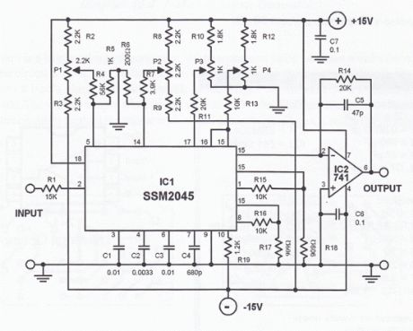
This audio processor circuit features the SSM2045 IC which was developed specially for electronic music applications and the 741 opamp IC. The circuit is configured as a low pass filter with a DC voltage control for gain. The input signal is set to a working level of 150mVpp through the resistor R1.How does the audio processor works
The filter has 2 buffered outputs: the 2-pole output at pin 1 and 4-pole output at pin 8. Internally, the outputs are connected to 2 voltage-controlled-amplifiers (VCA).The R15 and R16 are connected to these outputs to achieve optimum offset and control voltage suppression.
P4 is the volume control. The current that flows to the pins 15 and 16 should not go beyond the maximum of 250 µA. The balance of the two VCAs and the entire filter is being controlled be a voltage range of -250 mV to + 250 mV at pin 14.This voltage can be set by P2.
The input can be driven with source impedances up to a maximum of 200 Ω. With an input level of 0dBm, the VCA weakens by 6 dB. The bias current needed at pin 17 is between 120 µA and 185 µA. The cutoff frequency can be shifted between 20 Hz and 20 kHz with a variable voltage at pin 5. This can be varied through P1. The capacitor values were selected to give the filter its Butterworth characteristics.
The output current of the SSM2045 IC is converted to a voltage output by the 741 opamp. Any sybsequent circuit must be DC decoupled from IC2.The noise-voltage ration is about 80 dB.
Audio processor circuit schematic
Sent by Claudio, IT
3 Responses to “Audio Processor Circuit”
(View)
View full Circuit Diagram | Comments | Reading(1649)
DIY Tremolo Effect Circuit
Published:2012/9/19 21:21:00 Author:Ecco | Keyword: DIY , Tremolo Effect
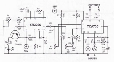
This tremolo effect circuit uses the XR2206 and the TCA730 IC which is designed as an electronic balance and volume regulator with frequency correction. The circuit is usefull for stereo channels and it also has the ability to simulate the Lesley effect aka rotating loudspeaker effect. How does the tremolo effect circuit works
Balance and volume settings are done with a linear potentiometer for both channels. If this potentiometer is replaced with an AC voltage source, a periodic modulation of the input signal can be achieved. This AC voltage source comes from the function generator IC XR2206. This IC generates square, triangle and sinewave signals but for this project we use only the sinewave.The modulation voltage can be varied with P1 from 1 Hz up to 25 Hz. Resistor R3 sets the operation level of the sinewave generator. R5 and R6 set the DC voltage and the sinewave amplitude at the output. C2 is a ripple filter. The squarewave output of the XR2206 drives T2 and a LED to optically display the frequency.The modulating voltage reaches pin 13 of TCA730 via P3 and R10. This input functions as the volume control or in this case the volume modulation. The degree of the balance modulation (Lesley effect) can be varied with P2. A regulated power supply using 7815 IC is recommended. Do not use a non-stabilized power supply since the current variations would influence the modulation negatively.Attach the 7815 IC to a good heatsink (about 10 cm2).
IC Tremolo effect circuit schematic
(View)
View full Circuit Diagram | Comments | Reading(1917)
Biofeedback by skin resistance
Published:2012/9/19 21:19:00 Author:Ecco | Keyword: Biofeedback , skin resistance
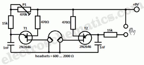
This simple circuit makes it possible for a particular type of biofeedback. The principle underlying the observation that a person’s skin resistance depends on the extent to which the person is relaxed; skin resistance increases with the depth of relaxation state.In the circuit shown, the skin resistance influence the oscillator frequency that is built with unijonction transistor T2. Both electrodes, which form a ring, are applied to two fingers of a hand. A speaker is used for hearing the sound whose height is a measure of the state of relaxation. The more profound state of relaxation is, the sound frequency is lower.
Relaxation monitor circuit schematic
The second oscillator, built with transistor T1, also produce a sound. In this case you can adjust the height of sound with potentiometer P1, at the frequency of the other oscillator, corresponding to the deepest state of relaxation. If the signals of the two systems are run separately in a stereo headset, the maximum relaxation is achieved when the right tone sounds at the same height at the left.
One Response to “Biofeedback by skin resistance”
Source: electroschematic.com
(View)
View full Circuit Diagram | Comments | Reading(965)
Kitchen Exhaust Fan Controlled by Temperature
Published:2012/9/19 21:19:00 Author:Ecco | Keyword: Kitchen Exhaust Fan, Controlled by Temperature

Exhaust fan is an important component in kitchens. Here is a simple circuit to control kitchen fans by monitoring the ambient temperature. It is built around the renowned precision integrated temperature sensor chip LM35 (IC1). Rest of the circuit is a non-traditional electromagnetic relay driver wired around the popular LED driver LM3914 (IC2). User can switch three presetted temperature levels using a jumper/slide switch (JP1), which determines the heat level to activate the relay and hence the electric exhaust fan wired through the relay contacts. It works off 12V DC power supply.
Kitchen Fan Controller Circuit Schematic
Only one adjustment is required in this kitchen exhaust fan controller circuit. After construction, set jumper point in its first position, ie base terminal of T1 is connected to pin 13 of IC2 and adjust the preset P1 carefully so that relay RL1 is energised when ambient temperature level reaches near 29oC. However this is not very critical as you can select any threshold level by connecting the jumper points to other unused output pins of IC2 (here only 3 outputs are used). More details about LM3914 and/or LM35 are available as pdf datasheet from NSC website.
Source: electroschematic.com (View)
View full Circuit Diagram | Comments | Reading(1986)
TinyCAD for schematic drawing
Published:2012/9/19 21:18:00 Author:Ecco | Keyword: TinyCAD, schematic drawing

TinyCAD is a program for drawing circuit diagrams commonly known as schematic drawings. It supports standard and custom symbol libraries. It supports PCB layout programs with several netlist formats and can also produce SPICE simulation netlists.TinyCAD is an open source schematic capture program for MS Windows.Use TinyCAD to produce professional circuit diagrams and export net list information to PCB applications.
Download TinyCAD from Project Home: tinycad.sf.net
Join the tinyCAD user group http://uk.groups.yahoo.com/group/tinycad/
3 Responses to “TinyCAD for schematic drawing”
(View)
View full Circuit Diagram | Comments | Reading(1261)
Polarity protection circuit
Published:2012/9/19 21:18:00 Author:Ecco | Keyword: Polarity protection

The most simple polarity protection tehnique is to connect a series diode to the power line input. The diode conducts only when the power supply protection is correct. But the incovenient is that at higher current levels, the voltage drops and power loss of the diode affects the power level adversely.This polarity protection circuit is dimensioned for 12 V power supplies and avoids the voltage and power loss problem. By correct polarity, the current flowing to the D1 and the relay coil causes the relay contacts to activate. The NO contact closes powering the electronic device. The NC contact opens and the current supplying the relay coil is reduced to a low level just enough to maintain relay activation.
Polarity protection circuit schematic
When reversed polarity occurs, the diode blocks the current and the relay cannot activate. The NO contact remains open and the electronic device is protected from the reversed polarity voltage.
3 Responses to “Polarity protection circuit”
Source: electroschematic.com (View)
View full Circuit Diagram | Comments | Reading(1191)
Battery Level Monitor circuit
Published:2012/9/19 21:15:00 Author:Ecco | Keyword: Battery Level, Monitor

This simple circuit can monitor the charging process in 12 Volt Lead Acid battery or Tubular battery. The status of LED indicates whether the battery is accepting charge or not. It also indicates the full charge condition.The circuit can be incorporated in any battery charger like 6 volt, 9 volt, 12 volt etc. The only change needed is replacement of the Zener ZD with appropriate value. That is for 6 volt charger , use 6.1 volt Zener and for 9 volt charger it should be 9.1 volt Zener.
Battery Level Monitor Circuit
The circuit is based on the switching of two NPN transistors (BC547) to drive the corresponding LED. Zener diode ZD is connected to the base of T1 so as to switch on T1 when the Zener conducts. This happens only when the battery voltage is above 12 volts. Green LED lights when the battery voltage is normal or battery attains full charge. Resistor R1 and Preset VR adjust the base bias of T1 for smooth switching. When T1 conducts, base of T2 will be pulled to ground and T2 turns off and Red LED extinguishes.
When the circuit is connected to the battery before charging the LED indications will be
1. If the battery voltage is above 12 volts (that is the normal terminal voltage of 13.8), Zener conducts and Green LED lights and Red LED remains off.2. If the battery voltage is below 12 volts, Zener remains non conducting and Green LED remains off and Red LED lights.3. When the battery is connected to the charger, and if the battery is accepting charge, Green LED goes off and Red LED remains on. When the battery attains full charge, Green LED lights and Red LED goes off.4. If the battery is not accepting charge, Green LED never lights, even after the prolonged charging. This indicates that the battery is not attaining the normal terminal voltage above 12 volts.
5 Responses to “Battery Level Monitor circuit”
(View)
View full Circuit Diagram | Comments | Reading(2031)
LDR = Light Dependent Resistor = Photoresistor
Published:2012/9/19 21:14:00 Author:Ecco | Keyword: LDR, Light Dependent Resistor , Photoresistor
You’re asking what is LDR? It stands for Light Dependent Resistor or Photoresistor, which is a passive electronic component, basically a resistor which has a resistance that varies depending of the light intensity. A photoresistor is made of a high resistance semiconductor that absorbs photons and based on the quantity and frequency of the absorbed photons the semiconductor material give bound electrons enough energy to jump into the conduction band. The resulting free electrons conduct electricity resulting in lowering resistance of the photoresistor. The number of electrons is dependent of the photons frequency.
How does the LDR (photoresistor) works
The resistance is very high in darkness, almost high as 1MΩ but when there is light that falls on the LDR, the resistance is falling down to a few KΩ (10-20kΩ @ 10 lux, 2-4kOmega; @ 100 lux) depending on the model.
Light dependent resistors come in different shapes and colors. LDRs are very useful in many electronic circuits, especially in alarms, switching devices, clocks, street lights and more. There are some audio application uses such as audio limiters or compressors. It is used to turn ON or OFF a device according to the ambient light.
On electroschematics.com we have some circuits that uses the photoresistor.They are all tagged as LDR. Here are some of them:
Light alarm circuit with LDRThis musical light alarm circuit is very simple, uses only 7 components, a LDR and a 3.6 V battery or 3 x 1.2 volts rechargeable batteries. The well-known UM66 is used as the sound generator and will give a pleasent wake up alarm.
LDR PC Desk LampMost of the PC desk lamps available in the market light up whenever there is an input power. These don’t take into account whether there is a real need for the light or not. Here is an intelligent PC desk lamp circuit that overcome the problem.
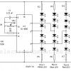
Christmas LED DecorationUsing this simple circuit, you can make an 18 LED flasher to decorate the X’Mas Tree. The White, Blue and Red LEDs flash at different rates to give a colorful display. It is a light sensitive circuit so that it will turn on in the evening automatically and stays on till morning.
Flashing LED with LDR with photoresistorIn this flashing led lights circuit, the LDR or photoresistor is connected in such way that when the light intensity varies it will influence the flashing frequency and the brightness of the LEDs. You can arrange the LEDs D1 to D (View)
View full Circuit Diagram | Comments | Reading(1172)
Flashing Lights Circuit
Published:2012/9/18 21:39:00 Author:Ecco | Keyword: Flashing Lights
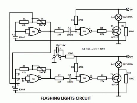
This flashing lights circuit can be used as beacon. The assembly consists basically of two blinking steps that commands two light bulbs. With the help of P1 you can adjust the flashing frequency between some limits.There are 2 parts for the circuit, the second one works the same way as the other but with the help of a wire bridge or a switch you can choose different operating modes.A bridge between M and 3 means: 2 independent blinks.If there is a bridge between M and 2, then the lamps lights alternatively with a frequency that can be adjusted with P1. And finally there is one more possibility for M and 1, where the lamps blinks at the same time.
The flashing lights circuit works with voltages between 3V and 15V.The lamps voltage must be 2/3 of working voltage. R5 and R10 are chosen so that the lamps are about to light.
Flashing Lamp Lights Circuit Schematic
3 Responses to “Flashing Lights Circuit”
(View)
View full Circuit Diagram | Comments | Reading(1283)
Telephone ringtone generator circuit
Published:2012/9/18 21:39:00 Author:Ecco | Keyword: Telephone ringtone generator

This is a simple home telephone ringtone generator circuit which is built with applying only several electronic components / parts. It generates simulated telephone ringtone and requires only DC supply with 4.5V DC to 12V DC voltage.One may possibly use this circuit in ordinary intercom or phone-type intercom. The sound is pretty loud when this circuit is operated on +12V DC power supply. Even so, the volume of ring sound can be adjusted.
Ringtone generator circuit schematic
CD4060B is chosen to produce three kinds of pulses. Preset VR1 is fine-tuned to get 0.3125Hz pulses at pin 3 of IC1. At the same time, pulses obtainable from pin 1 will be of 1.25 Hz and 20 Hz at pin 14. The three output pins of IC1 are connected to base terminals of transistors T1, T2, and T3 through resistors R1, R2, and R3, respectively.
Working with a built-in oscillator-type piezobuzzer generates about 1kHz tone. In this particular circuit, the piezo-buzzer is turned ‘on’ and ‘off’ at 20 Hz for ring tone sound by transistor T3. 20Hz pulses are obtainable at the collector of transistor T3 for 0.4-second duration. Just after a time interval of 0.4 second, 20Hz pulses become again obtainable for another 0.4-second duration. This is followed by two seconds of nosound interval. Thereafter the pulse pattern repeats by itself.
11 Responses to “Telephone ringtone generator circuit”
(View)
View full Circuit Diagram | Comments | Reading(1127)
SEN-1327 LPG Gas Sensor Module
Published:2012/9/18 21:38:00 Author:Ecco | Keyword: LPG, Gas Sensor, Module
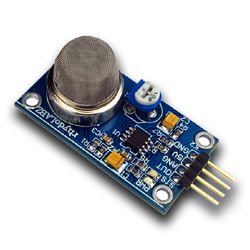

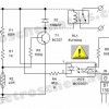
The SEN-1327 LPG Gas Sensor Module is designed to enable LPG detection interface to Microcontroller without ADC Channels. It allows to determine when a preset LPG gas level has been reached or exceeded. Interfacing with the sensor module is done through a 4-pin SIP header and requires One I/O pin from the host microcontroller.The onboard microcontroller provide initial heating interval after powerup and then starts to meassure LPG sensor output.If it found the LPG contents above setted value, it will inform the Host controller by pulling the Output Pin to High and Starts to blink a onboard status LED. The sensor module is mainly intended to provide a means of comparing LPG sources and being able to set an alarm limit when the source becomes excessive.
SEN1327 pins configuration and photo
SEN-1327 module features
Uses the MQ-6 LPG Gas Sensor
Easy SIP interface
Compatible with most microcontrollers
Onboard Status and Power LED
Onboard Pot for threshold setting
On board microcontroller
6 Responses to “SEN-1327 LPG Gas Sensor Module”
(View)
View full Circuit Diagram | Comments | Reading(3637)
L14F1, L14F2 Datasheet
Published:2012/9/18 21:37:00 Author:Ecco | Keyword: Datasheet
The L14F1/2 is a silicon photodarlington mounted in a narrow angle, TO-18 package.
L14F1 and L14F2 features
hermetically sealed package
narrow reception angle
One Response to “L14F1, L14F2 Datasheet”
(View)
View full Circuit Diagram | Comments | Reading(595)
LM338 datasheet
Published:2012/9/18 21:37:00 Author:Ecco
The LM138/LM238/LM338 are adjustable 3-terminal positive voltage regulators capable of supplying in excess of 5A over a 1.2V to 32V output range. They are exceptionally easy to use and require only 2 resistors to set the output voltage. Careful circuit design has resulted in outstanding load and line regulation comparable to many commercial power supplies. The LM138 family is supplied in a standard 3-lead transistor package.
LM338 features
GUARANTEED 7A PEAK OUTPUT CURRENT
GUARANTEED 5A OUTPUT CURRENT
ADJUSTABLE OUTPUT DOWN TO 1.2V
LINE REGULATION TYPICALLY 0.005% /V
LOAD REGULATION TYPICALLY 0.1%
GUARANTEED THERMAL REGULATION
CURRENT LIMIT CONSTANT WITH TEMPERATURE
STANDARD 3-LEAD TRANSISTOR PACKAGE
2 Responses to “LM338 datasheet”
(View)
View full Circuit Diagram | Comments | Reading(832)
| Pages:327/2234 At 20321322323324325326327328329330331332333334335336337338339340Under 20 |
Circuit Categories
power supply circuit
Amplifier Circuit
Basic Circuit
LED and Light Circuit
Sensor Circuit
Signal Processing
Electrical Equipment Circuit
Control Circuit
Remote Control Circuit
A/D-D/A Converter Circuit
Audio Circuit
Measuring and Test Circuit
Communication Circuit
Computer-Related Circuit
555 Circuit
Automotive Circuit
Repairing Circuit