
Circuit Diagram
Index 1858
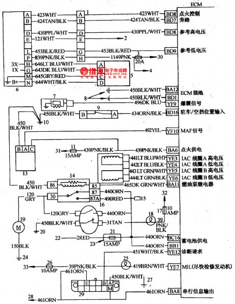
The engine control circuit of Buick-Century 3.3L(4)
Published:2011/5/17 20:19:00 Author:Borg | Keyword: engine control circuit, Buick-Century

The engine control circuit of Buick-Century 3.3L1-igniting switch wire 8-lead pin connector; 2-tachometer on the instrument(if there is); 3-oil injector coil fuse; 4-oil injector; 5-crank position sensor; 6-igniting control module; 7-explosive sensor; 8,10,20,7-transmission ground connection; 9-p/n switch; 11-ECM fuse; 12-idling speed control motor; 13-air flow meter; 14-fuel pump relay; 15-oil pump test connector; 16-engine oil pressure switch.
(View)
View full Circuit Diagram | Comments | Reading(1022)
The engine control circuit of Buick-Century 3.3L(3)
Published:2011/5/17 20:05:00 Author:Borg | Keyword: engine control circuit, Buick-Century
The engine control circuit of Buick-Century 3.3L(3)1-igniting switch; 2-air-conditioner fuse; 3-air-conditioner control switch; 4-air-conditioner high voltage switch; 5-air-conditioner low voltage switch; 6-engine/air-conditioner fuse; 7-air-conditioner clutch relay; 8-diode locked in bundles, about 3·8cm away from connector; 9-the right-rear ground connection of engine; 10-air-conditioner ground connection of compressor; 11-speed meter; 12-speed module tube pin D; 13-fun relay; 14-radiator fan; 15-P/S bracket ground connection. (View)
View full Circuit Diagram | Comments | Reading(902)
BA656-the integrated circuit of LED potential indicating driver
Published:2011/5/17 5:38:00 Author:Borg | Keyword: integrated circuit, LED


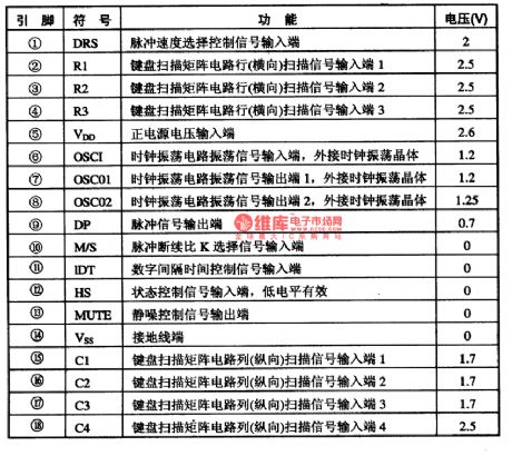
BA656 is an integrated circuit of LED potential indicating drive Toyo Power Tool Corp., Japan, which is used in simple instrument, voltage detection and demodulation circuits.1.the internal circuit and pin functions of BA656BA656 can directly drive 5 LED. This kind of potential indicating driver has 5 comparison circuits each level. It is in single 9-lead in-line package, whose internal circuit is shown in Figure 1, and its pin functions and data are listed in Table 1.
Figure1 the internal circuit of BA656
(View)
View full Circuit Diagram | Comments | Reading(3290)
The BA0331 3.3V integrated circuit of three terminal stable voltage
Published:2011/5/17 3:31:00 Author:Borg | Keyword: integrated circuit, stable voltage

BA0331 is an 3.3v integrated circuit of three terminal stable voltage, which is widely used in DVD and PDVD player at home or abroad as the power supply circuit in decoding circuits.function featuresThe stable circuit of BA0331 is 3.3v, which is special, and it specially provides power for MPEG2 decoding circuits. If it is broken, it is hard to find a substitute. Therefore, it can be replaced by a LM317 voltage stabler with two distributing resistances, or we can string up an IN5401 and 1N5402 to reduce the voltage from 5v to 3.6v as the substitute of 3.3v.
(View)
View full Circuit Diagram | Comments | Reading(1237)
The engine control circuit of Buick-Century 3.3L(2)
Published:2011/5/17 19:52:00 Author:Borg | Keyword: engine control circuit, Buick-Century

Figure 6-28 The engine control circuit of Buick-Century 3.3L1-oil injection coil fuses; 2-oil injector; 3-igniting switch coil 8-lead connector; 4-stable speed module tube; 5-momentum steering pressure switch; 6-transmission ground connection; 7,14,18-instrument fuse; overheat indicator; 9-engine/air-conditioner fuse; 10-active carbon jar magnetic valve; 11-4T60-only transmission; 12-TCC electric magnetic valve; 13,17-brake switch; 3T40-only transmission (View)
View full Circuit Diagram | Comments | Reading(959)
AY915lB-the integrated circuit of microcomputer dialing
Published:2011/5/17 5:50:00 Author:Borg | Keyword: integrated circuit, microcomputer dialing
AY915lB is an integrated circuit of microcomputer dialing, which is widely used in communication and phone circuits.1function featuresAY915lB contains pulse dialing process circuits, silence-noise control circuits, key switch encoding circuits and other function circuits.2.pin functions and dataAY9151B is in 18-lead dual in-line package, whose pin functions and data are listed in Table 1.Table 1 pin functions and data of AY9151B
(View)
View full Circuit Diagram | Comments | Reading(440)
The engine control circuit of Buick-Century 3.3L(1)
Published:2011/5/17 19:37:00 Author:Borg | Keyword: control circuit, Buick-Century
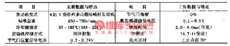
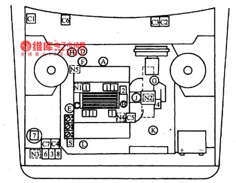
The engine control circuit of Buick-Century 3.3L is as shown in Figure 6-27 to Figure 6-30, whose sensors include: throttle position sensor; coolant temperature sensor, crankshaft position sensor; oxygen sensor, explosive sensor and air flow meter; and the sensors are here as transmission gear switches of input signals, momentum steering pressure switch, air-conditioner tube pressure switch and air-conditioner voltage switch.
Computer equipment: c1-engine computer; c2-diagnosis plug; c3-fault indicator; c4-computer/oil pump fuse (View)
View full Circuit Diagram | Comments | Reading(1020)
T24C16-1OPC(RA)--the electrically erasable programmable read-only ROM
Published:2011/5/17 8:24:00 Author:Borg | Keyword: electrically erasable programmable, read-only

AT24C161OPC(RA)--is an electrically erasable programmable read-only ROM of Ko (View)
View full Circuit Diagram | Comments | Reading(505)
The seatbelt protection system circuit of Buick-Century
Published:2011/5/17 22:15:00 Author:Borg | Keyword: protection system, Buick-Century
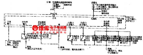
Usually, there are some warning systems, for example, when the igniting switch is connected but the seatbelt is off, and the doors are not closed well, the seatbelt warning lamp will flash, meanwhile, there are some buzzing from the clock warning; besides, some cars, such as Ford Taurus, which is fixed with auto seatbelt, when the door is open and the igniting switch is on, the seatbelt will automatically fix the driver in the chair along the chair track. If the driver want to get off, when he/she opens the door, the belt will go back to its former position, which is convenient for the driver to leave the seat.
(View)
View full Circuit Diagram | Comments | Reading(497)
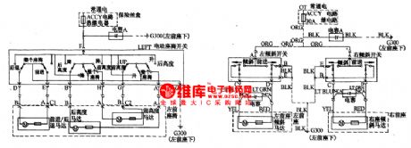
The multiple warning system circuit of Buick-Century
Published:2011/5/17 21:09:00 Author:Borg | Keyword: warning system, Buick-Century
The multiple warning system is fixed on the left-rear side of the I/p, which is near the body panel, it can buzz or flash when in dangerous or abnormal conditions.When the speed is too high, seat belt is not fixed, the igniting key is in when the car is off, parking lamps or large lights are on, car doors are not closed well and steering indicator is in, etc, the system will warn the driver in time. The input signals are all kinds of switch and signal voltages; the power supply comes from general fuse(15A, behind the instrument plate).
(View)
View full Circuit Diagram | Comments | Reading(473)
The electric window circuit of Buick-Century
Published:2011/5/17 21:27:00 Author:Borg | Keyword: electric window, Buick-Century
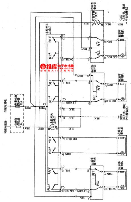
This circuit is the same with common cars, which has a general switch controlled by the driver, and there are separated switches controlled by passengers, when press head up , the glass will raise up, and vice versa. The elevation motor is a permanent micro D.C motor.
(View)
View full Circuit Diagram | Comments | Reading(779)
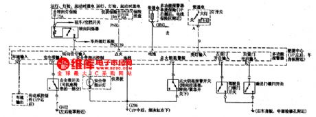
The remote controlled door lock circuit of Buick-Century
Published:2011/5/17 21:47:00 Author:Borg | Keyword: door lock, Buick-Century

The left-front lock switch is in parallel with right-front door lock, when the lock switch is at lock position, the lock relay will drive the 4 lock motors to lock all the doors; when the switch is in unlock state, the relay will make right-front, right-rear and left-rear door open, and the left-front door is opened by the driver.If there were no remote modules, such as in Figure 2,actions likeopening the door or locking the door would be done by keys or door lock switches.
(View)
View full Circuit Diagram | Comments | Reading(1396)
AN8485SB-El- the integrated circuit of 3-phase motor and loading motor drive
Published:2011/5/17 8:08:00 Author:Borg | Keyword: integrated circuit, 3-phase motor


AN8485SBEl- is an integrated circuit of 3-phase motor and loading motor drive (View)
View full Circuit Diagram | Comments | Reading(633)
Optical Fiber Data Transmission Coupling Circuit
Published:2011/5/17 1:21:00 Author:Sharon | Keyword: Optical Fiber, Data Transmission, Coupling
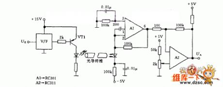
The first step is to transform input analog signal to frequency signal through input voltage frequency converter V/F and then send it to optical fiber by light-emitting diodes. The length of optical fiber or polystyrene rod depends on the separative voltage between digital or analog signals and the photodiode. Photodiode can drive a 100mA output operational amplifier A1, and can further drive cables, relays, or loudspeaker after being amplified byop-amp A2. LEDs can apply MV50 with output amount to 200mA. A1 can apply RC301 operational amplifier, and A2 RC311 can use operational amplifier.
(View)
View full Circuit Diagram | Comments | Reading(955)
Typical Application Circuit of M50460-012P IC
Published:2011/5/16 8:44:00 Author:Michel | Keyword: Application Circuit, IC


 Typical Application Circuit
Remote control typical application circuit composed of M50460-012P IC is showed as above.Picture:Typical Application Circuit of M50460-012P IC (View)
Typical Application Circuit
Remote control typical application circuit composed of M50460-012P IC is showed as above.Picture:Typical Application Circuit of M50460-012P IC (View)
View full Circuit Diagram | Comments | Reading(801)
The electric chair circuit of Buick-Century
Published:2011/5/17 21:18:00 Author:Borg | Keyword: chair circuit, Buick-Century
The positions of the driver or passenger chairs (front or back, high or low and the angle of the backrest)has a big affect on driving or passengers' comfort, passengers of different figures should adjust the position properly. The principle of the circuit is like to that of glass elevators.
(View)
View full Circuit Diagram | Comments | Reading(1657)
The fault code of 21 detection circuit of Daewoo ESPERO
Published:2011/5/17 6:16:00 Author:Borg | Keyword: fault code, detection circuit
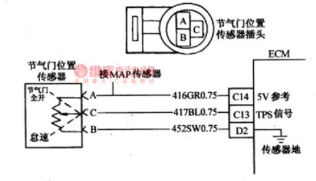

The fault code of 21 means that the signal voltage of throttle sensor is too high. TPS offers a signal that changes with throttle position, and the normal signal voltage is lower than 1.25v when at idling speed, and the voltage about 4.5V when the throttle is open. TPS is one of the most important input parameters, which is used to control the oil volume and other outputs by ECM. When the throttle is closed, the voltage should be lower than 1.25v, as the throttle is getting wide open, TPS voltage will raise up gradually.
(View)
View full Circuit Diagram | Comments | Reading(720)
AN8838SB-the integrated RF signal processing integrated circuit
Published:2011/5/17 8:42:00 Author:Borg | Keyword: signal processing, integrated circuit


AN8838SB is an integrated RF signal processing integrated circuit produced by Panasonic Corp., Japan, which is widely used in portable VCD players.1.function featuresAN8838SB is a energy-saving RF signal processing integrated circuit, which can shift the disc signals and state signals read out by laser heads into RF signals, in the meantime, it focuses errors and track error signals. The internal circuit of if is in Figure 1.
2.pin functions and dataAN8838SB is in 28-lead USONF package, whose working voltage ranges 2.4V-5.5V, and its pin functions are listed in Table 1.
(View)
View full Circuit Diagram | Comments | Reading(612)
The fault code of 24 detection circuit of Daewoo ESPERO
Published:2011/5/17 2:53:00 Author:Borg | Keyword: fault code, detection circuit, Daewoo ESPERO
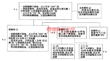
*1. This step is to check whether fault code 22 is actual or interrupted fault. The conditions of fault 22 are: the engine is running; TPS voltage is lower than 0.16V(160mV).*2.this step is to imitate the phenomena of fault code 22(see the cause of it), if it is flashing, then it means that ECM and its circuit are normal.*3. This step is check if the reference voltage of TPS send by ECM and sensor ground connection are good.*4. If No.416 circuit(V REF is 5v) is broken, ECM will save fault code of 34, too. (View)
View full Circuit Diagram | Comments | Reading(468)
Three-phase four-wire phase lack protection circuit
Published:2011/5/17 20:58:00 Author:TaoXi | Keyword: Three-phase, four-wire, phase lack, protection circuit

Because the current transformer's testing cost is too high, and the volume is big, so the switching power supplies always use the electronic phase lack protection circuit. Figure 5 is a simple electronic phase lack protection circuit. When the three-phase is balance, R1~R3's node H has the low level voltage, the optical coupling output is nearly the zero level. When the phase is lack, H's electric potential increases, the optical coupling output is high level, and it is compared by the comparator, then it outputs the low level voltage to blockade the driving signal. The standard of the comparator is adjustable, so you can adjust the phase lack action value. This phase lack protection circuit can be used in the standard of three-phase four-wire but not the three-phase four-wire.
(View)
View full Circuit Diagram | Comments | Reading(883)
| Pages:1858/2234 At 2018411842184318441845184618471848184918501851185218531854185518561857185818591860Under 20 |
Circuit Categories
power supply circuit
Amplifier Circuit
Basic Circuit
LED and Light Circuit
Sensor Circuit
Signal Processing
Electrical Equipment Circuit
Control Circuit
Remote Control Circuit
A/D-D/A Converter Circuit
Audio Circuit
Measuring and Test Circuit
Communication Circuit
Computer-Related Circuit
555 Circuit
Automotive Circuit
Repairing Circuit