
Circuit Diagram
Index 1845
TV remote controller 02
Published:2011/5/19 8:14:00 Author:TaoXi | Keyword: TV, remote controller
TV remote controller 02 (View)
View full Circuit Diagram | Comments | Reading(612)
TV remote controller 10
Published:2011/5/19 8:11:00 Author:TaoXi | Keyword: TV, remote controller
TV remote controller 10 (View)
View full Circuit Diagram | Comments | Reading(566)
TV remote controller 11
Published:2011/5/19 8:11:00 Author:TaoXi | Keyword: TV, remote controller
TV remote controller 11 (View)
View full Circuit Diagram | Comments | Reading(510)
Roll-pattern type wireless remote control circuits TH150/TH150A/TH150B
Published:2011/5/12 3:17:00 Author:TaoXi | Keyword: Roll-pattern, wireless remote control
The internal structure of the roll-pattern type wireless remote control circuit is very complex, the coding method is also very special, but the usage of this circuit is the same as the digital coding circuit, even more simple. The radio control circuit which is composed of the rolling code decoding circuits TH150/TH151A/TH151B. The radio transmission circuit (which is composed of the rolling code circuit, the TH150 and the transistor carrier frequency oscillator): The super-regenerative wireless remote control receiver circuit (which is composed of the TH151A/B rolling decoding circuit): (View)
View full Circuit Diagram | Comments | Reading(533)
Voltage Amplifier Circuit Made up of LF356 and Others
Published:2011/5/20 19:55:00 Author:leo | Keyword: Voltage Amplifier Circuit Made up of LF356 and Others, LF356

What the picture 1 shows is a voltage amplifier circuit which is made up of LF356 and others. The voltage gain of this circuit is decided by the ratio of R1 and R2( R3 and R4).It can be calculated through the parameters that are shown in the picture that voltage gain is about 20 dB. R1 and R2 can make up of a degenerative circuit which is also be called small local hysteresis loss circuit that can prevent the circuit from close or uncommon oscillation. VD1 and VD2 are protection circuits of input port. (View)
View full Circuit Diagram | Comments | Reading(3567)
MC3359-Narrow band FM ZF integrated circuit diagram
Published:2011/5/22 1:43:00 Author:leo | Keyword: MC3359-Narrow band FM ZF integrated circuit diagram

MC3359 is a type of narrow band FM ZF integrated circuit which applies to frequency modulation of ZF circuit in duplex operation communication devices.
1.Function features:The integrated circuit MC3359 contains mixer circuit, oscillator, amplitude limiter, noise limitation detection, demodulator and other circuits.
2.Pin functions:MC3359 has two kinds of packages: one is 18-pin dual lie and the other is 20-pin patch(1 and 20 are NC while 2 to 19 pin correspond 1 to 18 pin). The picture gives all detailed information about the 18 pins. (View)
View full Circuit Diagram | Comments | Reading(1142)
Power Amplifier Circuit Diagram Formed by CA3094 and Others
Published:2011/5/20 22:28:00 Author:leo | Keyword: Power Amplifier Circuit Diagram Formed by CA3094 and Others, CA3094

As what is shown in the picture, this is a power amplifier circuit which is made up of CA3094 and others. CA3093 contains a output transistor with the maximum output current of 100mA and OTL audio amplifier used for 8Ω load with bootstrap transistor as well as tone control circuit and so on. In the circuit, VT2 and VT3 can form a complementary type emitting following bootstrap circuit. VT1 offers biasing and compensates temperature, which also decides the operating point of AB type amplifiers. C2 is bootstrap capacitor which is used to improve the drive voltage of amplifier. Tone control circuit is located in the load feedback circuit of operating amplifier to acquire better frequency feature. (View)
View full Circuit Diagram | Comments | Reading(2265)
MC13135-Wireless receiving demodulation integrated circuit diagram
Published:2011/5/21 22:12:00 Author:leo | Keyword: MC13135-Wireless receiving demodulation integrated circuit diagram

MC13135 is a type of receiving demodulation interated circuit which is applied in receiving demodulation of antenna in communication.
1.Function features:The integrated circuit MC13135 consists of dual conversion circuit, local oscillator circuit, mixer circuit, filed intensity detection circuit, audio pre-amplifying circuit, medium frequency signal amplifying circuit and other related circuits.
2.Pins functions and data:The integrated circuit MC14433 adopts 24-pin dual line package. The arrangement and functions of its pins are as what is shown in the picture.
Note: If it cannot receive wireless signals, please check whether 22 pin of MC13135 can receive signals or not. If it is ok, please check whether the dual conversion signals of 18 pin is common or not. (View)
View full Circuit Diagram | Comments | Reading(894)
MC14433-A/D Converting Integrated Circuit Diagram
Published:2011/5/21 21:46:00 Author:leo | Keyword: MC14433-A/D Converting Integrated Circuit Diagram
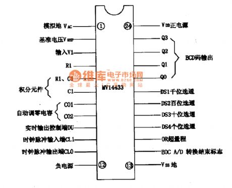
MC14433 is a kind of A/D converting integrated circuit produced by Motorola in USA which is widely applied in the multimeter that has a LED whose automatic range can show 3 1/2.
1.Function features:MC14433 contains a BCD code generating circuit, DS1-DS4 gate circuit of ones, tens, hundreds and thousands, A/D converting circuit, automatic zero set control circuit, voltage circuit of the base power supply as well as other related circuits.
2.Pins function and dataThe integrated circuit MC14433 adopts 24-pin dual line package. The arrangement and functions of its pins are as what is shown in the picture. (View)
View full Circuit Diagram | Comments | Reading(999)
MC68HSO5P4DW-Communication single chip microcomputer integrated circuit diagram
Published:2011/5/22 1:58:00 Author:leo | Keyword: MC68HSO5P4DW-Communication single chip microcomputer integrated circuit diagram

MC68HSO5P4DW is a kind of communication single chip microcomputer integrated circuit produced by Motorola in USA which is widely applied in wireless telephones.
1.Function features:The integrated circuit MC68HSO5P4DW is used to carry out impulse, two-tone compatible dial, input and output of various control signals, receiving detection and manually/automatically converting of various command signals.
2.Pin function and data:The integrated circuit MC68HSO5P4DW adopts 28-pin duel lie patch package. The picture gives the detailed information about its pin function and related data. (View)
View full Circuit Diagram | Comments | Reading(604)
temperature sensor compensation circuit
Published:2011/5/23 19:36:00 Author:John | Keyword: temperature sensor
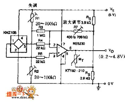
The sensor KTY series in the circuit is applied for positive or negative temperature drifting compensation. In many cases, temperature drifting of KMZ10B is negative. And an op-amp NE52300 is placed in the circuit to achieve the following functions:
1. Average (sensor to sensor) the sensitivity of temperature drift.2. Apply the potentiometer R1 and R2 for offset adjustment. 3. Use the potentiometer RT for gain adjustment.
(View)
View full Circuit Diagram | Comments | Reading(2611)
Complementary tube multivibrator circuit
Published:2011/5/23 20:11:00 Author:John | Keyword: Complementary tube multivibrator
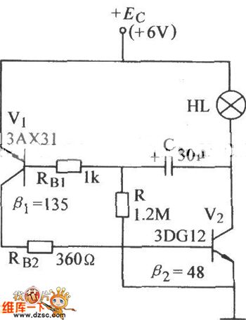
Complementary tube multivibrator circuit is shown below.
(View)
View full Circuit Diagram | Comments | Reading(622)
Electronic voltage vibration circuit
Published:2011/5/23 20:12:00 Author:John
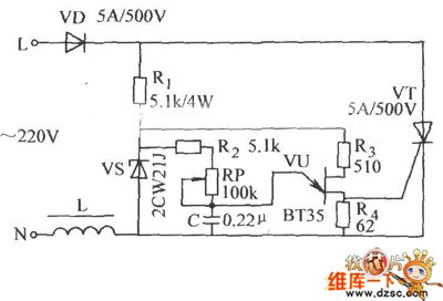
Electronic voltage vibration circuit is shown below.
(View)
View full Circuit Diagram | Comments | Reading(575)
UHF transmitter module CS901 composed of the SAW
Published:2011/5/13 0:44:00 Author:TaoXi | Keyword: UHF, transmitter module, SAW
UHF transmitter module CS901 is composed of the SAW (View)
View full Circuit Diagram | Comments | Reading(705)
Security wireless transmitter circuit of the adytum and the bank
Published:2011/5/13 0:43:00 Author:TaoXi | Keyword: Security wireless transmitter, adytum, bank
Security wireless transmitter circuit of the adytum and the bank (View)
View full Circuit Diagram | Comments | Reading(492)
Remote control transmitter circuit composed of the TX4915
Published:2011/5/12 1:05:00 Author:TaoXi | Keyword: Remote control transmitter
Remote control transmitter circuit is composed of the TX4915. (View)
View full Circuit Diagram | Comments | Reading(573)
radio transmitting typical application circuit composed of the MC2833
Published:2011/5/13 0:43:00 Author:TaoXi | Keyword: radio transmitting, typical application
radio transmitting typical application circuit is composed of the MC2833 (View)
View full Circuit Diagram | Comments | Reading(579)
Infrared remote control music socket circuit 2 PH303A
Published:2011/5/12 6:50:00 Author:TaoXi | Keyword: Infrared remote control, music socket circuit
The PH303A×2 infrared pulse transmitter circuit is as shown, by adjusting the RP1 you can make the oscillation frequency to12kHz.
Infrared remote control receiver circuit: (View)
View full Circuit Diagram | Comments | Reading(535)
radio transmitting typical application circuit composed of the MC2831
Published:2011/5/13 0:43:00 Author:TaoXi | Keyword: radio transmitting, typical application
radio transmitting typical application circuit is composed of the MC2831 (View)
View full Circuit Diagram | Comments | Reading(505)
555 acupuncture point detector circuit
Published:2011/5/23 7:48:00 Author:TaoXi | Keyword: acupuncture point, detector
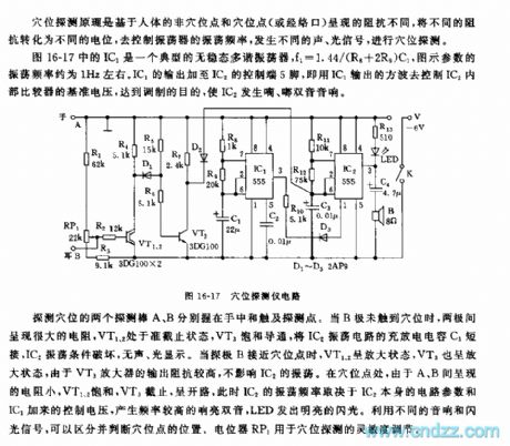
As the figure 16-17 shows, IC1 is a typical astable multivibrator, f1=1.44/(R8+2R9)C1, the parameters' oscillation frequency in the figure is about 1Hz. IC1's output adds to the pin-5of IC2's control port, that uses IC1's output square wave to control IC2 internal comparator's reference voltage, so we achieve the purpose of modulation, IC2 sends out the diplophonia of di du .
At the acupuncture point, the resistance between A and B is small, so VT1 and VT2 is saturated, VT3 cuts off, at this time IC2's oscillation frequency depends on the circuit parameters of IC2 itself and the control voltage of IC1, this circuit produces the higher frequency loud diplophonia, and the LED issues the flashlight.
(View)
View full Circuit Diagram | Comments | Reading(1986)
| Pages:1845/2234 At 2018411842184318441845184618471848184918501851185218531854185518561857185818591860Under 20 |
Circuit Categories
power supply circuit
Amplifier Circuit
Basic Circuit
LED and Light Circuit
Sensor Circuit
Signal Processing
Electrical Equipment Circuit
Control Circuit
Remote Control Circuit
A/D-D/A Converter Circuit
Audio Circuit
Measuring and Test Circuit
Communication Circuit
Computer-Related Circuit
555 Circuit
Automotive Circuit
Repairing Circuit