
Circuit Diagram
Index 1844
INA166 Adding Output Current Buffer Circuit
Published:2011/5/21 21:55:00 Author:Robert | Keyword: Output Current, Buffer

The INA166 Adding Output Current Buffer Circuit is shown in the picture below. It is added BUF634 at the INA166's output port to connect the wide bandwidth. BUF623 is B-B company's 250mA high-speed buffer to extend the output current. INA166's output voltage detecting port Sense should be connected to the output port of BUF634 to detect the output voltage Vo precisely.
(View)
View full Circuit Diagram | Comments | Reading(1210)
INA217 Low-Noise Low-Distortion Instrument Amplifier Pin Circuit
Published:2011/5/22 0:38:00 Author:Robert | Keyword: Low-Noise, Low-Distortion, Instrument, Amplifier, Pin

The INA217 is a low-noise, low distortion monolithic instrumentation amplifier. With its design of current feedback circuit it can be used in low voltage level audio signals' amplification such as symmetric low-resistance miniature microphone (microphone) signal amplification. INA217 has low noise and wide bandwidth. So it can be used in many industrial, instrumentation and medical applications. Its special distortion elimination circuit can minimize the distortion. With 200Ω source impedance the INA217 provides the low-noise performance which almost closing to the theoretical value.With the excellent performance ofdifferential input, low noise and low distortion, it provides professional miniature microphone (mike) signal amplification.
(View)
View full Circuit Diagram | Comments | Reading(1118)
INA217 Input Stable Network Circuit
Published:2011/5/22 0:42:00 Author:Robert | Keyword: Input, Stable Network

The INA217 Input Stable Network Circuit is shown in the picture below. A very low signal-source internal resistance (less than 10Ω) can cause the INA217 to have self-oscillation. If two small inductances and small resistances are added in the input port to make up a network, it can minimize the self-oscillation's trend. If needed, it can add the inductance and resistance network to limit its self-oscillation.
(View)
View full Circuit Diagram | Comments | Reading(1392)
Temperature Control Circuit Composed Of T-121 Temperatrue Sensor
Published:2011/5/22 0:48:00 Author:Robert | Keyword: Temperature, Control, Sensor

The controlled temperaturepoint can be set by adjusting RP1 and RP2. The 555 time-base circuit makes up the schmitt out-phase circuit. It uses the relays to achieve the equipment's automatical control. The T-121 temperature sensor makes the temperature control circuit which is shown below.
(View)
View full Circuit Diagram | Comments | Reading(851)
50kHs Frequency Light Transmitting Circuit
Published:2011/5/22 0:58:00 Author:Robert | Keyword: 50kHs, Light, Transmitting

This circuit uses the pulse speed control system with central frequency of 50kHs. It takes the feedback to the transmitting audio signals to change the pulses speed. Thus it would drive the LED coupled to the optical fiber. The LED uses General Electric Company's LED55C or other similar LED. The optical transistor at the other end of the optical fiber would receive and decode the light signals to return the audio signals.
(View)
View full Circuit Diagram | Comments | Reading(541)
Car Turing Alarm (LD7208 Specific IC) Application Circuit
Published:2011/5/22 1:24:00 Author:Robert | Keyword: Car, Turing, Alarm, Specific IC, Application
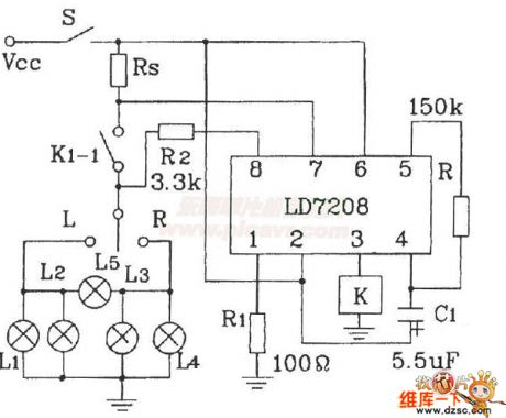
The Car Turing Alarm (LD7208 Specific IC) Application Circuit is shown in the picture below. This circuit's main functions are: when it is working normally and the car lamp is intact, the car lamp and the driver seat's monitoring lights would flash toghter and the flash frequency is 80 per minute. Once the car lamp is damaged, the monitoring light's flash frequency would speed up to double to alarm.
(View)
View full Circuit Diagram | Comments | Reading(474)
Low-Drift Constant Current Source Circuit Composed Of MIC2951
Published:2011/5/22 2:04:00 Author:Robert | Keyword: Low-Drift, Constant Current Source

The Low-Drift Constant Current Source Circuit Composed Of MIC2951 is shown in the picture below. Its constant current source's output current is: IL=1.23V/R. In this formula, the value of R should not make the MIC2951's output current exceed 150mA. The accuracy of R is required as the principle of 1%.
(View)
View full Circuit Diagram | Comments | Reading(1153)
Modulaor Circuit
Published:2011/5/22 2:19:00 Author:Robert | Keyword: Modulaor

The picture shows the peak value rectifier's voltage doubler circuit which is used as the test-head circuit. It is used to control the high resistance display circuit loop (FET voltage meter). It can work under high-frequency conditions because all high-frequency components are all using very short lead. If the length of the lead is no more than 2mm, this circuit can work at the VHF area.
(View)
View full Circuit Diagram | Comments | Reading(453)
LED Modulator Circuit
Published:2011/5/22 2:27:00 Author:Robert | Keyword: LED, Modulator

This circuit uses the overlay typetransistors. This transistor's transmitting area is made up by several little transmitting area. And there is a layer of metal overlaying on it to make the transmitting area connected. So it could get large-power outputunder high-frequency conditions.
In this circuit it is requiredshielding. In communication system it can be used to modulate thebeam of light.
(View)
View full Circuit Diagram | Comments | Reading(634)
Condensation Sensors Application Circuit
Published:2011/5/22 2:32:00 Author:Robert | Keyword: Condensation Sensors, Application

Condensation sensors can be used in video recorders and other a variety of humidity control circuits. This picture shows the bathroom mirror automatic moisture removal device which is made by the condensation sensor.
(View)
View full Circuit Diagram | Comments | Reading(601)
Operational Amplifier Of Double Power Supply And Single Power Supply Circuit
Published:2011/5/22 2:53:00 Author:Robert | Keyword: Operational Amplifier, Double Power Supply, Single Power Supply


For the circuit in picture (a), it uses double power supply, in-phase input, its amplification factor is:V=+Ua/Ue=(R1+R2)/R2, 1MΩ>R3>10kΩ, R2>1kΩ, V<200.For the circuit in picture (b), it uses double power supply, out-phase input, so:V=Ua/Ue=R1/R2, 1MΩ>R3>10kΩ, R2>1kΩ, V>200.For the circuit in picture (c), it uses single power supply, in-phase input, so:V=+Ua/Ue=(R1+R2)/R2, 1MΩ>R3 and R3>10kΩ, R2>1kΩ, V<200, 1/wC1<0.5R2.For the circuit in picture (d), it uses single power supply, out-phase input, so:V=-Ua/Ue=R1/R2, 1MΩ>R3 and R3>10kΩ, R2>1kΩ, V<200, 1/wC1<0.5R2.
(View)
View full Circuit Diagram | Comments | Reading(702)
Integration (Quadrature) Demodulation Circuit
Published:2011/5/22 3:03:00 Author:Robert | Keyword: Integration, Quadrature, Demodulation

In this picture, the photodiode array is irradiated from the communication system's LED and then it would convert the light signals on the broadcast band. The circuit is similar with the 1:1 balanced-unbalanced converter and it has the single-channel input and double-channel output. The phase-shifting between the two output is 90°. The circuit would not require neutralization. It can give reasonably the high gain with low noise response.
(View)
View full Circuit Diagram | Comments | Reading(1094)
Standard Computer Interface Data Bus Circuit Composed Of LM35DZ Celsius Temperature Sensor And A/D Converter
Published:2011/5/22 3:56:00 Author:Robert | Keyword: Standard, Computer, Interface, Data Bus, Celsius, Temperature Sensor, A/D Converter

The Standard Computer Interface Data Bus Circuit Composed Of LM35DZ Celsius Temperature Sensor And A/D Converter is shown in the picture below.
(View)
View full Circuit Diagram | Comments | Reading(1101)
TSV Type Temperature Sennor Typical Application Circuit
Published:2011/5/22 4:04:00 Author:Robert | Keyword: TSV Type, Temperature Sennor, Application

This circuit's output voltage Vo's temeratrue sensitivity is 10mV/°C. The resistance R is current-limit resistance. The capacitor C is used to improve the stability of the circuit. When the test position and the result-reading position have a far distance, the wire resistance's voltage drop would cause some extent measuring errors.
(View)
View full Circuit Diagram | Comments | Reading(706)
The circuit of ICL7103A high precision digital voltmeter
Published:2011/5/20 0:17:00 Author:Borg | Keyword: high precision, digital voltmeter

The figure is a circuit of ICL7103A high precision digital voltmeter. This circuit is a 4.5 bit digital voltmeter circuit. ICL8052A contains reference voltage, but the voltage can't meet the minimum need of long stability, therefore, it needs to connect a reference power supply of high temperature stability from outside, the voltage is formed by LM3999. There are some problems to notice when we are assemble the circuit: the analog spot and digital spot are completely separated, there is only a ground connection near the circuit; and when we print the design of the circuit board, the digital signal induction to the analog is to be noticed.
(View)
View full Circuit Diagram | Comments | Reading(2805)
The luminous flux test circuit with optical resistors
Published:2011/5/20 0:55:00 Author:Borg | Keyword: luminous flux, test circuit, optical resistors

This is a luminous flux test circuit with optical resistors. In the circuit, the optical resistor RG forms a bridge with RP1,RP2,R1 and R2; RP1 is used to adjust the balance of the bridge; RP2 is used to adjust the sensitivity of the circuit. If we adjust RP1 to make the voltages on a and c are equal, then VTl and VT2 stop, and the thyristor of VSI is off. In the meantime, if the resistance of RG changes, the bridge will be unbalanced, and a voltage will be generated among a-c, then VTI and VT2 are on, the thyristor of VSI is also on, the buzzer B will buzz to inform the luminous flux of the test.
(View)
View full Circuit Diagram | Comments | Reading(1580)
The closing door reminder circuit (1)
Published:2011/5/23 4:43:00 Author:Borg | Keyword: reminder circuit

See as in Figure 13-1, the circuit consists of a trigger relay circuit and an integrated music circuit. When the fridge door is open, the touch switch (K) is linked to the power supply, as the voltage on the terminal of C1 can not be changed suddenly, on the trigger terminal 2-pin of 555, there is a positive peak voltage(>2/3VDD) trigger which can reset the circuit, and the 3-pin is in low LEV, so VT1 is blocked. The capacitor of C1 charges with R1 and RP1, when the voltage on the 6-pin is 1/3 VDD lower than trigger voltage, 555 will be posited and the 3-lead is in high LEV, then VT1 is conducting and IC2 gets power and make sounds to remind the master of opening the door.
Figure 13-1 The closing door reminder circuit (1) (View)
View full Circuit Diagram | Comments | Reading(1274)
The power failure protection circuit of 555
Published:2011/5/23 5:28:00 Author:Borg | Keyword: power failure, protection circuit
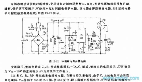
It's a taboo for fridge to get power in intermittence, especially off and on in short times. To avoid the compressor is on and off repeatedly and to protect it from damage, it is proper to use this circuit to protect it temporarily. This circuit consists of step-down rectifier circuits, 555 relaying circuit and controllable trigger circuits, see as Figure 13-22.
AC step-down rectifier circuit consists of C1,R1,bridge rectifier D1~D4 and C2, the rectified current becomes a CD voltage of VDD=10V after being stabilized by R2 and DW, then it becomes a continuing working voltage. (View)
View full Circuit Diagram | Comments | Reading(569)
Power-supply of adjustable DC steady voltage
Published:2011/5/23 7:55:00 Author:Ariel Wang | Keyword: adjustable, DC , steady voltage
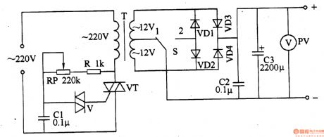
Adjust the resistance of RP.It can change the conduction angle of VT. Then it can change the power-supply of DC steady voltage of input voltage and output voltage.
The 220V AC voltage is adjusted through electronic voltage regulation switch,dropped down through T,commutated through VD1-VD4 and filtered through C2,C3. Then it generates DC voltage needed.
Put S to position 1 ,VD3 and VD4 make up a full wave commutated circuit. At this time the power-supply of DC steady voltage is low voltage output.Put S to position 2 ,VD1-VD4 make up a three-phase-bridge rectifier circuit. At this time the power-supply of DC steady voltage is high voltage output.
(View)
View full Circuit Diagram | Comments | Reading(597)
Practical temperature controller circuit
Published:2011/5/13 0:59:00 Author:TaoXi | Keyword: Practical temperature controller
Practical temperature controller circuit (View)
View full Circuit Diagram | Comments | Reading(379)
| Pages:1844/2234 At 2018411842184318441845184618471848184918501851185218531854185518561857185818591860Under 20 |
Circuit Categories
power supply circuit
Amplifier Circuit
Basic Circuit
LED and Light Circuit
Sensor Circuit
Signal Processing
Electrical Equipment Circuit
Control Circuit
Remote Control Circuit
A/D-D/A Converter Circuit
Audio Circuit
Measuring and Test Circuit
Communication Circuit
Computer-Related Circuit
555 Circuit
Automotive Circuit
Repairing Circuit