
Circuit Diagram
Index 1855
Triode Transistor PD160F80 Internal Circuit
Published:2011/5/17 5:49:00 Author:Robert | Keyword: Triode Transistor, Internal

The Triode Transistor PD160F80 Internal Circuit is shown below.
(View)
View full Circuit Diagram | Comments | Reading(387)
Jinuoer Brand BCD-170 Refrigerator Circuit
Published:2011/5/17 5:40:00 Author:Robert | Keyword: Jinuoer Brand, Refrigerator

The Jinuoer Brand BCD-170 Refrigerator Circuit is shown below.
(View)
View full Circuit Diagram | Comments | Reading(531)
Triode Transistor PE110F160 Internal Circuit
Published:2011/5/17 5:41:00 Author:Robert | Keyword: Triode, Transistor, Internal Circuit

The Triode Transistor PE110F160 Internal Circuit is shown below.
(View)
View full Circuit Diagram | Comments | Reading(424)
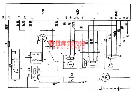
The engine power-control system circuit of Tianjin Toyota 8A-FE
Published:2011/5/17 22:36:00 Author:Borg | Keyword: power-control systemToyota


Tianjin Automobile Industry launched the Xiali TJ7131U at the turn of the century, which is fixed with the 8A-FE engine produced by Tianjin Toyota Corp.. The engine has 4 cylinders and 16 valves, power controlled petrol multiple jets, dual overhead camshafts, closed-loop control and triple catalysis transformers, the emission is 1.31L, rated output power is 63kW/6000rpm, and the largest torque is 1lON·m/5200rpm。
Like other power jet engine, the control system of 8A-FE can also control the stableness of idle speed, the pollution of exhaust and fault detection, etc.
(View)
View full Circuit Diagram | Comments | Reading(1452)
CXP912032-an integrated microcomputer circuit of single door
Published:2011/5/17 23:33:00 Author:Borg | Keyword: integrated microcomputer, single door


CXP912032 is a 16-bit integrated microcomputer circuit of CMOS single door produced by Sony for KHM-210AAA DVD.1.Function featuresCXP912032 contains 16 bit SPC9O0 CPU, 1281KB ROM and 6144 RAM. And it is also fixed with the series connector unit, 8 bit A/D and D/A transformer, 14 bit PWM, halt controller and servo-controlled circuit and clock circuit, etc.
Figure 1-1 the internal circuit of CXP912032
2.Pin functions and dataCXP912032 is in 100-lead QFP package.Table 1-2 Pin functions and data of CXP912032
(View)
View full Circuit Diagram | Comments | Reading(457)
DYMK-2- the integrated circuit of switching power supply thick films
Published:2011/5/16 20:40:00 Author:Borg | Keyword: integrated circuit, power supply, thick films

DYMK-2 is an integrated circuit of switching power supply thick films, which is suited in modifying and replacing series switching power supply of all kinds of color TV sets.1.pin functions and dataDYMK-2 is in 5-pin single in-line package, whose pin functions and data are listed in 1-1.
2.InstructionsIn Table 1-1, ① and ④ are the hot-ground detection, while ③ is the cold-ground detection.Color TV screens smaller than 54cm are installed with 21-Ⅱ module, while screens of 60cm are installed with 25-Ⅱandscreens larger than 74cm are installed with 29-Ⅱ. (View)
View full Circuit Diagram | Comments | Reading(582)
The fault code 51 and 54 detection circuit of Daewoo ESPERO
Published:2011/5/17 1:13:00 Author:Borg | Keyword: detection circuit, Daewoo ESPERO


The computer codes of 51 and 54 represent the potentiometer is malfunctioning, which is used to adjust the CO content in the emission. CO potentiometer is an adjustable resistance to control the delivering signal voltage to ECM. After the repairing, the CO content in the engine emission is supposed to be 0.3%~0.5% , in the normal condition, the D8 signal voltage on ECM plug should be 0.08~3.8V. The output signal of CO potentiometer is one of the signals that control the fuel injection, whose circuit connection are shown in Figure 28.
(View)
View full Circuit Diagram | Comments | Reading(1616)
BA3515AFS-the integrated reproducing circuit of single door stereo
Published:2011/5/16 20:43:00 Author:Borg | Keyword: integrated reproducing circuit, single door

BA3515AFS is an integrated reproducing circuit of single door stereo produced by Toyo Power Tool Corp., Japan, whose pin functions and data are listed in Table 1.
Table 1 pin functions and data of BA3515AFS (View)
View full Circuit Diagram | Comments | Reading(416)
Electronic controlled detection circuit of Santana 2000GLi
Published:2011/5/16 20:46:00 Author:Borg | Keyword: detection circuit, Santana

When detecting electronic controlled petrol spay system, we should use digital multimeter (V.A.Gl526 or V.A.G.1715) and LED tube detection light(V.A.G1598). To avoid directly contacting the connector of computer controller,the computer detection box (V.A.G1598) and its assistant cables should be in use.The condition: battery voltage is normal; computer controller and fuel pump fuse are normal; oil pump and its relay are normal; the ground connection of the engine on the air cylinder cover is normal.
(View)
View full Circuit Diagram | Comments | Reading(610)
The fault code of 34 diagnosis circuit of Daewoo ESPERO
Published:2011/5/18 0:06:00 Author:Borg | Keyword: fault code, detection circuit, Daewoo ESPERO
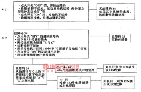
The fault code of 34 means that the signal voltage of manifold absolute pressure(MAP) sensor circuit is low and degree of vacuum is high, whose circuit condition is the same as fault 33.
*1. this is to make sure whether fault 34 is generated in the actual or interrupted condition, the generating conditions of fault 34 are: fault 21 has not been detected (the TPS signal voltage of throttle is high); the rotationl speed is less than 1200r/min; the reading of MAP signal voltage is less than 14kPa; the rotationl speed is more than 1200r/min; TPS is less than 20% (voltage is lower than 1V which is higher than that when throttle gate is closed).
(View)
View full Circuit Diagram | Comments | Reading(456)
The diagnosis circuit of fault code 24 of Daewoo ESPERO
Published:2011/5/18 0:05:00 Author:Borg | Keyword: fault code, detection circuit, Daewoo ESPERO
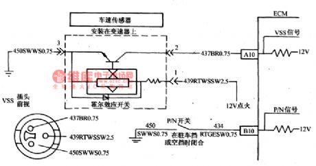
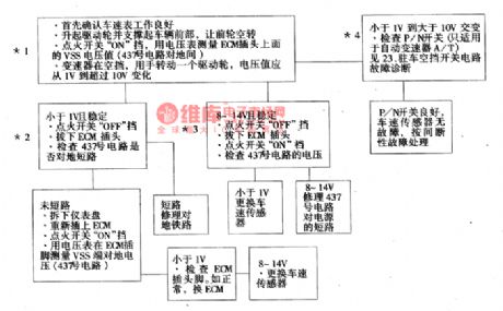
Computer ECM provides 12V voltage to speed sensor through the No. 437 circuit, and then the voltage goes back along the circuit. When the driven wheels run, the sensor makes the No.437 circuit connect the ground in turn, this pulse signals are generated 3683/1.6Km, and ECM counts the speed with the pulse time.The condition of generating the fault of 24: the coolant temperature is higher 85℃, the pressure of admission is lower than 4gkPa (MAP) and the engine rotating speed ranges 1500~4400rpm, the parking/neutral gear indicator is not at the parking or neutral gear, speed sensor shows the car speed is lower than 8km/h, all the conditions mentioned above last for more than 3S.
(View)
View full Circuit Diagram | Comments | Reading(830)
BA1362F-the stereo decoding integrated circuit of PLL frequency modulation(FM)
Published:2011/5/16 20:48:00 Author:Borg | Keyword: integrated circuit, PLL, frequency modulation(FM)


BA1362F is a stereo decoding integrated circuit of PLL frequency modulation produced by Toyo Power Tool Corp., Japan, which is used in micro radios of 1.5V as a decoding circuit.1.the internal circuit and pin functions of BA1362FBA1362 uses PLL technology, which can separate balance audio signals from compound stereo signals. It characterizes with advantages of low working voltage and good decompression function, and its gain can be adjusted to +2.5dB and 0dB. Since the internal of the input circuit is connected well, so the outward elements won't be necessary. The internal circuit of the chip is shown in Figure 1.
(View)
View full Circuit Diagram | Comments | Reading(1540)
BAll02FS-the integrated Dolby B noise reduction circuit
Published:2011/5/17 23:38:00 Author:Borg | Keyword: noise reduction, single door


BAll02FS is an integrated Dolby B noise reduction circuit of single door produced by Toyo Power Tool Corp., Japan, which is widely used in all kinds of stereos to reduce the ground noise in recording/reproducing.1.the internal circuit and pin functions of BAll02FSBAll02FS contains sub-circuits of buffering amplifier, peak value suppression, feedback amplifier and assistant wave-detection channel amplifier, whose main characters are: two dependent noise reduction channels, electric recording/producing and noise reduction switches.This IC is in 24-lead dual line plastic package.
(View)
View full Circuit Diagram | Comments | Reading(2303)
The detection circuit of Daewoo ESPERO No.23 and 25 fault codes
Published:2011/5/17 4:37:00 Author:Borg | Keyword: detection circuit, fault codes
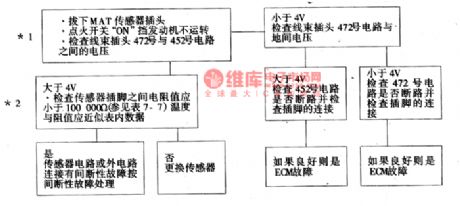
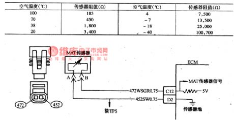
Fault code of 23 means the signal voltage of air temperature sensor is too high,(MAT) and the 25 means it is too low.Admission manifold air temperature sensor controls the signal voltage to ECM with a thermistor(see as Figure 18). ECM imposes a reference voltage(4~6V) on a sensor in No.427 circuit, when the air temperature is low, the resistance of the sensor (thermistor) is high, so ECM will get a high signal voltage. As the air gets warmer, the resistance of the sensor is getting lower, and the voltage is getting lower.
(View)
View full Circuit Diagram | Comments | Reading(1121)
Magnetic stirring apparatus circuit diagram 2
Published:2011/5/18 6:03:00 Author:Lucas | Keyword: Magnetic stirring apparatus

The magnetic stirring apparatus circuit is composed of the power circuit, mixing motor control circuit, heating thermostat circuit, mixing motor speed control circuit, timing alarm circuit and timing control circuit, the circuit is shown as the chart. The power circuit is composed of the power switch S1, the power transformer T, rectifier bridge pile UR1, resistor R1, power indicator HL1 and filter capacitor C2. Heating thermostat circuit is composed of heating switch circuit S3 (S3-l, S3-2), electric contact thermometer Q2, resistors R4 ~ R7, capacitors C1 and C3, the transistor V2 ~ V5, electric heater EH, temperature indicator HL3, heating lamp HL4, diode VD2, relay K3, potentiometers RP2 and RP3, thyristor VT and rectifier bridge UR2 and UR3. (View)
View full Circuit Diagram | Comments | Reading(1241)
The brief introduction of the Buick car produced by Shanghai GM Corp.
Published:2011/5/18 Author:Borg | Keyword: brief introduction, Buick, Shanghai
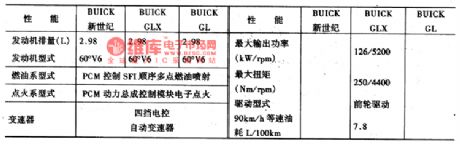
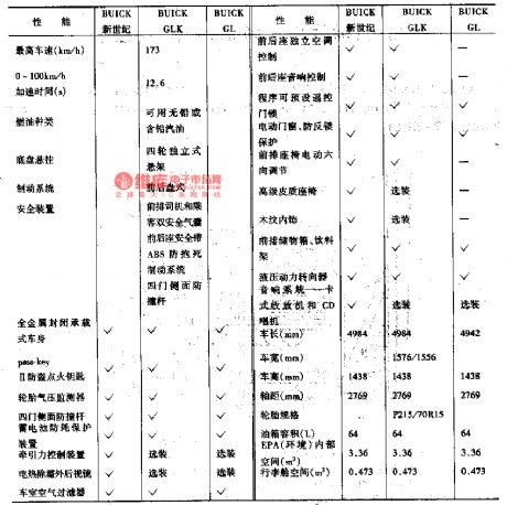
Shanghai GM Corp. Ltd is the largest Sino-US joint venture, which is joint-ventured by Shanghai Automotive Industry Corporation(Group) and GM,the USA, by far, 1.52 billion dollars have been invented in it. And the Buick cars produced by it will reach the high standard of the world, the main feature parameters are listed in Table 6-2.1.the engine and auto transmission3.0 L 60°V6 4-course petrol engine, high efficiency, low noise, good momentum,oil injection and electric igniting system with fuel-saving FI sequence multiple terminals, slight pollution.PCM momentum general computer control module will control and adjust automatically control the system according to the engine load, road condition, altitude and atmosphere, by which the engine can keep high efficiency and low oil consumption. 4-gear electrically controlled transmission can regulate the transmitting time, keep the best functions and smooth transmission in accordance with different conditions.
(View)
View full Circuit Diagram | Comments | Reading(526)
Plastic bag sealing machine circuit diagram 1
Published:2011/5/18 19:38:00 Author:Lucas | Keyword: Plastic bag , sealing machine

The plastic sealing circuit is composed of power circuit, control circuit and heating circuit, the circuit is shown as the chart. Power supply circuit is composed of rectifier diode VD1, filter capacitor C1 and the step-down resistors R1, R2. Control circuit is composed of control button S, resistors R3, R4, potentiometer RP, capacitor C2, diode VD2, transistor V, voltage regulator diode VS, thyristor VT, light-emitting diode VL and relay K. Heating circuit is composed of normally open contact K and power transformer T, heater EH. Adjusting the resistance of RP can change the charging time of C2, thus change the EH heating time to adapt the sealing with different thickness and material.
(View)
View full Circuit Diagram | Comments | Reading(13738)
The cruise control circuit of Buick-Century
Published:2011/5/18 0:04:00 Author:Borg | Keyword: cruise control, Buick-Century
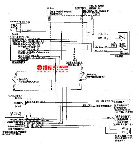
Car cruise control system can automatically keep a certain speed according to the driver's request without the driver pressing the plate, which can release the driver from tiredness and improve the comfort. In spite of the wind or the angle of the road, the car speed can be kept the same, which can reduce the oil consumption and the exhaust emission. The system consists of control switch, speed sensor and cruise control ECU, etc.
(View)
View full Circuit Diagram | Comments | Reading(516)
Motorcycle burglar alarm circuit diagram
Published:2011/5/17 19:41:00 Author: | Keyword: Motorcycle, burglar alarm

Transmitter: the relay K and SCR VS are used to control the power of transmitter circuit. IC1 forms alarm sound signal circuit. The transistor V and its peripheral components form RF oscillator circuit to transmit the alarm signal. When the circuit is in the waiting state, the switch S1 is connected, and SB1 is disconnected(the front lock is locked), K is in the release state, the alarm transmitter does not work. When the front lock is opened (SB1 is connected), VS is triggered and turned on, K pulls in, the transmitter gets power. When SB1 is switched on, the normal open point of K-2 will be self-locking, at this time, the S1 being disconnected can stop the alarm.
(View)
View full Circuit Diagram | Comments | Reading(2112)
The idling speed detection and basic parameter setting circuit of Santana 2000GLi
Published:2011/5/16 7:58:00 Author:Borg | Keyword: idling speed, basic parameter, Santana
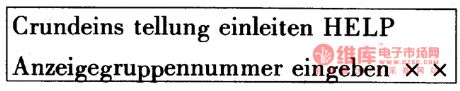
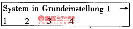

Idling speed is an operating mode of the engine, it's also useful for other operating mode detection if we exactly detect the main idling speed parameters, such as igniting angle of advance, the revolutions of the engine, the content of carbon monoxide and oil throughput.Before detection was taken, the engine coolant temperature should be no less than 80℃ , and the power supply voltage of the computer control should be higher than 12.2V, air-conditioning and other electrical equipment should be turned off, ventilation system should be without leakage, throttle is normal and the front wheels point to the head.The idling speed standard values of AFE engine are as follows.
(View)
View full Circuit Diagram | Comments | Reading(398)
| Pages:1855/2234 At 2018411842184318441845184618471848184918501851185218531854185518561857185818591860Under 20 |
Circuit Categories
power supply circuit
Amplifier Circuit
Basic Circuit
LED and Light Circuit
Sensor Circuit
Signal Processing
Electrical Equipment Circuit
Control Circuit
Remote Control Circuit
A/D-D/A Converter Circuit
Audio Circuit
Measuring and Test Circuit
Communication Circuit
Computer-Related Circuit
555 Circuit
Automotive Circuit
Repairing Circuit