
Circuit Diagram
Index 1857
Electronic Mouse Killer (5)
Published:2011/5/16 4:44:00 Author:Sue | Keyword: Electronic, Mouse Killer
When a mouse touches the sensor between A,B, V1 and V2 will be connected and C3 begins to charging. When the voltage reaches a certain level, V3 and V4 will be connected, making K connected, and the alarm circuit and high voltage output circuit begin to work. IC will output music signals, which will drive BL to make a warning sound. The other circuit will send the alarm signal through W, which can be received by the users within 1km with a FM radio. At the same time, VL1 and VL2 are illuminated, high voltage generator begins to oscillate and generate a pulse high voltage, which will kill the mouse. (View)
View full Circuit Diagram | Comments | Reading(1740)
Ward Caller Four
Published:2011/5/18 8:46:00 Author:Felicity | Keyword: Ward Caller,
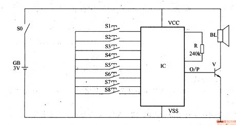
Turn the power switch on, and the circuit is electrified. While S1-S8 is not pressed, O/P port of IC has no output, and BL is noiseless. Once one of the S1-S8 buttons is pressed, IC will be triggered on. And O/P port outputs an electrical signal of the sound effect( Press S1-S8 in order, and O/P port of IC outputs “ Bed number one calling, Bed number two calling...Bed number 8 calling ), and then the electrical signal is amplified by V to drive BL sends out a simulative voice. And the medical personnel can know the number of calling bed according to the vocal calling number. (View)
View full Circuit Diagram | Comments | Reading(453)
Simple and practical constant temperature controller circuit
Published:2011/5/18 18:55:00 Author:TaoXi | Keyword: Simple, practical, constant temperature controller

The working principle is: ST is the WTQ-288 type electrical contact point pressure type thermometer, when the temperature of incubator reduces to the lower limit, ST's pointer contacts with the lower limit contact point, the bidirectional thyristor is forced to trigger conduction, and you connect heater RL's power supply, so the temperature of incubator rises. ST's pointer turns and separates from the lower limit contact point. Although the trigger circuit is disconnected, but for the capacitance C's phase shifting effect, when the supply voltage crosses zero, the capacitive current is not zero, so when the power is inverted, it still provides the trigger current for the triac to keep the conduction. (View)
View full Circuit Diagram | Comments | Reading(1080)
Simple delay timing circuit
Published:2011/5/18 10:42:00 Author:TaoXi | Keyword: Simple, delay timing
Simple delay timing circuit (View)
View full Circuit Diagram | Comments | Reading(652)
Holiday color light with disco sound circuit
Published:2011/5/16 9:41:00 Author:Christina | Keyword: Holiday color light, disco sound circuit

The circuit is as shown. It is composed of the clock pulse generator, the counter / divider circuit, the disco analog sound circuit and the AC step-down rectifier circuit.etc.
(View)
View full Circuit Diagram | Comments | Reading(1169)
ultrasonic repeling mosquito device
Published:2011/5/16 9:38:00 Author:Christina | Keyword: ultrasonic, repeling mosquito

The ultrasonic ultrasonic repeling mosquito device
This is one kind of extremely simple ultrasonic repeling midge, bug, cockroach circuit.
This relaxation oscillation circuit is composed of the CMOS 4047 monostable trigger, you can make it's center frequency to 22KHz by adjusting the 4K7, then the signal is output by the bridge type power which is composed of four transistors to promote the 3.25 inch Piezo to send out ultrasonic signal. (View)
View full Circuit Diagram | Comments | Reading(1207)
Practical 3-button interlock electronic switch circuit
Published:2011/5/16 18:50:00 Author:Christina | Keyword: Practical, 3-button, interlock, electronic switch

The circuit structure is simple, when you press any key, the corresponding channel opens. And the contact point's jitter does not affect the circuit's working, so this circuit has the good anti-interference performance.
If you remove the rear driver transistor, the circuit's static power consumption is nearly zero.
If you remove the button, this circuit can be used to control the pulse. (View)
View full Circuit Diagram | Comments | Reading(886)
multi-bit counter circuit used to performance
Published:2011/5/16 18:44:00 Author:Christina | Keyword: multi-bit counter, performance
This counter circuit can be used in the demonstration teaching and the science and technology exhibition applications, every bit of this counter is composed of the decimal counter RS7490, the RS7447 decoder and the 7 segment digital tube. If you want to add two stages more, the monitor must gets to the number of 9999 to start a new count cycle. The diode 1N914 which connects with the battery can be used to prevent the wrong polarity of power supply, and you need to reduce the power supply voltage to 5V to meet the integrated circuit's need.
(View)
View full Circuit Diagram | Comments | Reading(495)
Amplifier circuit uses the frequency to control the gain
Published:2011/5/16 9:07:00 Author:Christina | Keyword: Amplifier, frequency, gain

The amplifier circuit that uses the frequency to control the gain is as shown. Frequency gain control circuit uses the different input clock frequencies to control the amplifier gain. As the figure (a) shows, this circuit is composed of two parts: the analog switch and the integrated amp. The analog switch is composed of two pieces of the precise capacitance switch LTC1043; the integrated operational amplifier uses the JFET input op amp type LT1056.
(View)
View full Circuit Diagram | Comments | Reading(539)
Low Power AC/DC General Motor Thyristor Control Circuit
Published:2011/5/18 19:32:00 Author:Robert | Keyword: Low Power, AC/DC, General, Motor, Thyristor, Control

This circuit is used in the case of AC/DC general series wound motor stepless speed variation. Armature winding is in series with field winding through the thyristor. By the single-phase half-wave phase-shifting commutating control method, the thyristor's control angle could be changed by adjusting the 500ω potentiometer. So it can make the rotate speed be stepless adjusted from zero to the maximum value. This circuit is widely used in small household appliances such as blenders, sewing machines, hand drills and woodworking machinery.
(View)
View full Circuit Diagram | Comments | Reading(3565)
DC Motor Driving Circuit
Published:2011/5/18 10:03:00 Author:Robert | Keyword: DC Motor, Driving

The DC Motor Driving Circuit is shown below.
These are two DC motor driving circuit, one is driven by electric bridge while the other is driven by integrated circuit L293DD, which is used to drive two DC motor (12V, 80mA). On the other hand, for L293DD input port,maybe it can make the IN1, IN2 (IN3, IN4) connected toghter separately and controlled by a MCU port.
(View)
View full Circuit Diagram | Comments | Reading(1491)
Stepper Motor General Driving Circuit
Published:2011/5/18 7:17:00 Author:Robert | Keyword: Stepper Motor, General, Driving

The Stepper Motor General Driving Circuit is shown below.
The integrated system uses small type stepper motor, which is not highly required on voltage and current. Tointroduce the application principle, this circuit uses the simplest driving circuit which aiming at verifying the use of stepper motor. When using in normal industrial control it needs to improve from this base model. General driving circuit can shown in picture as follow.
(View)
View full Circuit Diagram | Comments | Reading(491)
Small Electric Heater Temperature Control Circuit Composed Of Three-Wire Serial Interface Smart Temperature Sensor DS1620
Published:2011/5/18 7:08:00 Author:Robert | Keyword: Electric Heater, Temperature Control, Three-Wire, Serial, Interface, Smart, Temperature Sensor

The Small Electric Heater Temperature Control Circuit Composed Of Three-Wire Serial Interface Smart Temperature Sensor DS1620 is shown in the picture below. When t<tL, TL would output high voltage level, which would set the 1/2CD4044 type RS trigger to be 1 and Q=1. This wouldmake the TMOS FET 2N6659 connected and also make the small electric heater's power connected. The 2N6659's UDSO=35V and PD=6.25W.
(View)
View full Circuit Diagram | Comments | Reading(2581)
Two-Wire Serial Interface Smart Temperature Sensor TCN75 And 89C51 MCU Interface Circuit
Published:2011/5/18 6:49:00 Author:Robert | Keyword: Two-Wire, Serial, Interface, Smart, Temperature Sensor, MCU

The interface circuit of TCN75 and 89C51 is shown in the picture below. Byletting the TCN75's address input ports A2~A0 all connect to high voltage level UDD, the address code is changed to be 111. The 89C51 can achieve the chip-selection function by software. The 89C51's series data receiving port (RXD) and series data transmitting port (TXD) are connected to the TCN75's SDA port and SCL port separately. TCN75's interrupt/compare signal is connected to 89C51's interrupt port INT0.
(View)
View full Circuit Diagram | Comments | Reading(1028)
The amplifier circuit diagram of 6p14 tube
Published:2011/5/17 21:10:00 Author:Ecco | Keyword: amplifier , tube

Each channel only needs two tubes. The amplification effect is divided into two parts which is based on the network. The first part is the voltage amplification part and the latter part is the penultimatestage and power amplifier stage. VE1, VE2 select 6N2 high μ pipe to improve the machine sensitivity. The major technical indicators of voltage amplifier stage are amplification times and frequency distortion. 6N2 amplification factor is 97.5, which is enough to meet the local requirements. Using resistance-capacitance coupling, the amplification of intermediate region is in the largest times, amplitude frequency and phase frequency characteristics are very flat.
(View)
View full Circuit Diagram | Comments | Reading(833)
Improving sound quality of F15 power amplifier circuit diagram
Published:2011/5/17 21:21:00 Author:Ecco | Keyword: Improving , sound quality , power amplifier
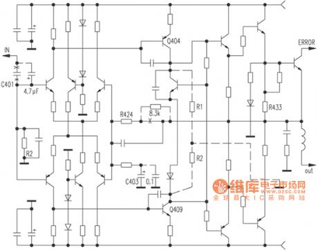
According to the figure, this is a fully symmetrical, full complement, double differential circuit. Firstly, the C401 10μF ordinary electrolytic input capacitor should be replaced by a 4.7μF CBB capacitor; then both ends of the feedback blocking capacitor C403 are added the WIMA 0.1μF capacitor, this would obviously make the sound be more smooth and clear; the second step, for improving the open-loop instructions, motivation level Q404, Q409 should be added 10kΩ collector load resistors R1, R2, while the feedback resistor R424 is connected a 8.3kΩ resistor in series, this can give a more natural sound with better transient, while the gain does not decrease and increase slightly.
(View)
View full Circuit Diagram | Comments | Reading(682)
Glanz WP700 two repairing cases of microwave circuit diagram
Published:2011/5/17 21:02:00 Author:Ecco | Keyword: Glanz two repairing cases , microwave

Example 1 Symptom: When it turns on, the furnace lights are lit, dial is in normal operation, but does not heat. Analysis on repairing: the reasons may be the high voltage circuit malfunction or no microwave output caused by magnetron. When people open the shell, the high-voltage fuse has been blown. According to the machine circuit (see photo) analysis, it may caused by the high current overload, and the reason may be a high voltage capacitor C breakdown, high voltage diode D breakdown, or magnetron breakdown. People should check the normal high voltage diodes, and then check the high voltage capacitor C, if they find breakdown, they should test machine after replacement, the trouble is removed.
(View)
View full Circuit Diagram | Comments | Reading(901)
The fault code of 33 detection circuit of Daewoo ESPERO
Published:2011/5/17 4:34:00 Author:Borg | Keyword: fault code, Daewoo
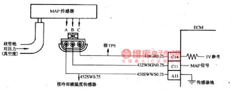
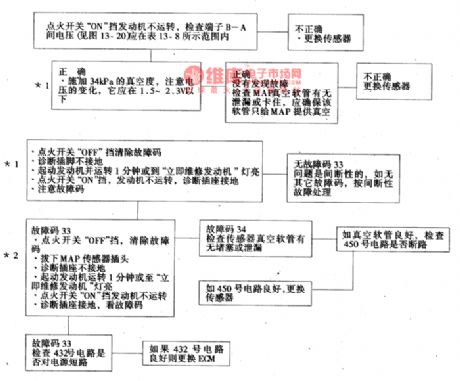
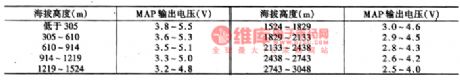
The fault code of 33 means that the signal voltage of manifold absolute pressure(MAP) sensor circuit is high and degree of vacuum is low. Manifold absolute pressure(MAP) sensor responds to the change of the pressure(vacuum drgree). When the igniting switch is at ON gear and the engine is still, the manifold pressure is larger than the atmospheric pressure, signal voltage is high, the ECM will use the signal as the parameter of car altitude and atmosphere pressure. When the engine is at idling speed, the MAP signal voltage values are as shown in Figure 20 and Figure 4.
MAP sensor check of admission manifold is shown as follows.
(View)
View full Circuit Diagram | Comments | Reading(1293)
The circuit of Chevrolet-Lumina 2.2L
Published:2011/5/17 6:32:00 Author:Borg | Keyword: Chevrolet-Lumina, circuit

The Lumina produced by Chevrolet of GM,USA, is fixed with 4-cylinder water cooling petrol engine, whose emission is 2.2L, and computer control multiple points (4 injecters) inject fuel at the same time, the admission in under control. The components layout is shown in Figure 7-1.
Figure 7-1 the component layout of Lumina 2.2LComputer equipment: C1-chief computer; C2-detection plug; C3-fault indicator; C4-oil pump/ computer fuse; C5-computer ground connection; C6-fuse box; C8-power supply center on the left of the engine (View)
View full Circuit Diagram | Comments | Reading(1100)
The electric rear-view mirror circuit of Buick-Century
Published:2011/5/17 22:26:00 Author:Borg | Keyword: rear-view mirror, Buick-Century
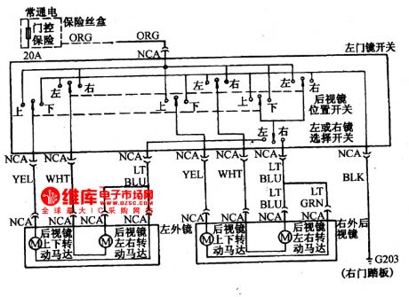
As the electric mirror circuits of other cars, the vertical adjustment of Buick-Century is done by the up/down switches, the horizon adjustment is done by the right/left switches, and the left or right mirror is set with a selective switch.
(View)
View full Circuit Diagram | Comments | Reading(649)
| Pages:1857/2234 At 2018411842184318441845184618471848184918501851185218531854185518561857185818591860Under 20 |
Circuit Categories
power supply circuit
Amplifier Circuit
Basic Circuit
LED and Light Circuit
Sensor Circuit
Signal Processing
Electrical Equipment Circuit
Control Circuit
Remote Control Circuit
A/D-D/A Converter Circuit
Audio Circuit
Measuring and Test Circuit
Communication Circuit
Computer-Related Circuit
555 Circuit
Automotive Circuit
Repairing Circuit