
Circuit Diagram
Index 1846
555 vision care mndatory rest 10 minutes power supply socket circuit
Published:2011/5/23 8:01:00 Author:TaoXi | Keyword: vision care, mndatory rest, 10 minutes, power supply socket

This power supply socket circuit is composed of the step-down rectifier circuit, the voltage-stabilizing circuit, the ultra-low frequency oscillator and the SCR control circuit.etc, as the figure 16-33 shows.
The step-down rectifier circuit outputs the +6V stable voltage. The ultra-low frequency astable multivibrator is composed of the IC2(555) and the R2,RP1,R3,C3. When you close the power supply switch SA, C3's charging voltage can not be mutated, so pin-2 has the low electric potential at the beginning to make the 555 in the setting state, and pin-3 outputs the high electric potential, the SCR conducts, the socket CZ gets the power to turn on the electrical equipments or lights.
(View)
View full Circuit Diagram | Comments | Reading(761)
555 sleep induction unit circuit
Published:2011/5/23 18:54:00 Author:TaoXi | Keyword: sleep, induction unit
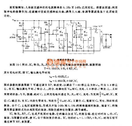
As the figure 16-1 shows, the astable multivibrator is composed of the IC1 and R1,R2,RP1,D1,C1, the oscillation period T=0.693(R1+R2+RP1)C1.
The figure parameters' oscillation period T can be changed by adjusting RP1, it is about 80 seconds as well; tcharging is about 0.8 second. When IC1 outputs the high electrical level, J and J1-1 close, the power voltage VDD charges the C5. After 0.8 second, J releases, J1-1 returns to the closing state, the R4 is connected, so the C5's charging voltage gets through the R4 and R5.
(View)
View full Circuit Diagram | Comments | Reading(857)
555 learning time too long reminding circuit
Published:2011/5/23 7:31:00 Author:TaoXi | Keyword: learning time, too long, reminding circuit

This learning time reminding circuit will remind you every one hour when you are learning or working to protect the eye and the body. This circuit is composed of the integral point lightspot coupler, the trigger control circuit and the controllable audio oscillator.etc. The circuit is as shown in figure 16-32.
The integral point is led out by the digital clock tenths unit LED digital tube's b segment. Under the action of the integral point moment jumping signal, the IC1's phototransistor has the low resistance, VT1 conducts, VT2 is in the saturated conduction state.
IC2 uses the time base circuit 555, and the monostable trigger is composed of the time base circuit 555 and the R2,C2.
(View)
View full Circuit Diagram | Comments | Reading(616)
555 mini electronic massager circuit
Published:2011/5/23 6:53:00 Author:TaoXi | Keyword: mini, electronic massager
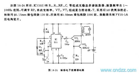
As the figure 16-24 shows, the astable multivibrator is composed of the IC(555) and R1,R2,RP1,C1, the oscillation frequency is between 1 to 100Hz, you can change the frequency by adjusting RP1. The composite promoting stage is composed of the VT1 and VT2, T1 uses the E140 ferrite core, the primary stage is binded with 120 turns of enamel insulated wire (the diameter is 0.15mm), the secondary stage is binded with 5000 turns of enamel insulated wire (the diameter is 0.08mm). The transducer uses the FY35-1A piezoelectric ceramic.
(View)
View full Circuit Diagram | Comments | Reading(1543)
555 acupuncture therapy and massage therapy instruments circuit
Published:2011/5/23 6:42:00 Author:TaoXi | Keyword: acupuncture therapy, massage therapy instruments
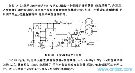
As the figure 16-23 shows, the treatment equipment uses the 555 as the core, and the audio multivibrator is composed of the 555, the signal is boosted by the transformer T1 and then produces the amplitude adjustable pulse.
The astable multivibrator is composed of the 555 and R1,R2,C1, the oscillation frequency f=1.44/(R1_2R2)C1, it is about 35Hz, the pulse width is about 17ms. The transformer T1 uses the small radio output transformer, and this transformer is reversed. The output amplitude is about 80V. You can connect the acupuncture needle, the counter electrode and the piezoelectric ceramics to the CK jack.
(View)
View full Circuit Diagram | Comments | Reading(1377)
555 amblyopia treatment rear shape therapy control circuit
Published:2011/5/23 6:30:00 Author:TaoXi | Keyword: amblyopia, treatment, rear shape therapy, control circuit

As the figure 16-27 shows, the astable multivibrator is composed of the 555 and R1,R2,RP1,RP2,RP3, the oscillation periods are:
T=tcharging+tdischargingtcharging=0.693(R1+RP1+R2+RP2)C1tdischarging=0.693(R2+RP1+RP2)C1
You can change the frequency and the duty ratio by adjusting the RP1,RP2,RP3, at the initial treatment, the frequency of 50 times per minute is better, then, you can improve the frequency to 70-80 times per minute. When the switch K2 cuts off, the light time is about 1 minute; when K1 cuts off, K2 opens, the treatment light will cyclical changes.
(View)
View full Circuit Diagram | Comments | Reading(489)
555 floodlight ultrasonic remote controller circuit
Published:2011/5/23 5:30:00 Author:TaoXi | Keyword: floodlight, ultrasonic, remote controller

As the figure 17-39 shows, the controller is composed of the ultrasonic remote control circuit and the control circuit, and it can be used in the application of light remote control switch.
The astable multivibrator is composed of the 555 and the R1,RP1,C1, the oscillation frequency f=1.44/(R1+RP1)C1, by adjusting the RP1, we can keep the frequency between 40kHz+/-500Hz. The ultrasonic transmitter head uses the UCM40T piezoelectric sensor.
If we adjust the RP1 on the output frequency load, the LM567 input signal will be larger than 25mV, the output port pin-8 has the low electrical level, VT3 is saturation conduction, SCR is trigger conduction, the light turns on.
(View)
View full Circuit Diagram | Comments | Reading(501)
555 photo amplifier sequence controller circuit
Published:2011/5/23 4:19:00 Author:TaoXi | Keyword: photo amplifier, sequence controller

This circuit has the functions of automatic timing exposure, automatic shifting filter and focus light automatical turn-on, and it can be used in the automatic operation of the black and white photograph amplifier.
As the figure 17-3 shows, the automatic and manual timing circuit is composed of the IC2,IC2(F3140) and IC3(555), we can choose the automatic timing mode or the manual timing mode by K2. In automatic timing exposure process, K2 is in the position of 2 , we connnect the photocell (2CR41) probe to the IC1's input port, and adjust RP3 to make the IC2's pin-6 to output the level signal which is higher than 0V.
(View)
View full Circuit Diagram | Comments | Reading(802)
555 household electric hot compress humidity control circuit
Published:2011/5/23 19:47:00 Author:TaoXi | Keyword: household, electric, hot compress, humidity control

As the figure 16-11 shows, the temperature control circuit is composed of the regulated DC power supply, the timing circuit and the temperature control circuit.etc. The 1~30 minutes timing circuit is composed of the 555 and RP1,R5,C5.etc. The length of time depends on the values of RP1,R5 and C5. td=1.1(RP1+R5)C5, you can change the timing time by adjusting RP1. When you are using this circuit, press the switch AN, the 555 output (pin-3) becomes the 11V high potential as the power supply of the IC3 thermostatic circuit. At the same time, the timing begins. The R10,C7 integral circuits have the same function with the R4,C3 integral circuits of IC2.
(View)
View full Circuit Diagram | Comments | Reading(1157)
555 intermittent type ozone generator circuit
Published:2011/5/23 19:18:00 Author:TaoXi | Keyword: intermittent type, ozone generator
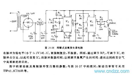
The ozone generator circuit is as shown in the figure 16-38, it is composed of the low-voltage power supply circuit, the ultralow frequency pulse oscilation circuit, the high-frequency multivibrator and the high-frequency pulse excitation stage.etc.
The low-frequency multivibrator is composed of the IC2(555) and R1,R2,D1,D2,RP1,C3, the oscillation frequency f=1.44/(R1+R2+RP1)C3.
The figure parameter's oscillation frequency is about 0.025HZ, the oscillation period is 40 seconds. By adjusting RP1, you can change the duty ratio of the oscillation pulse. The controllable multivibrator is composed of the IC3(555) and R5,R6,C5, the oscillation frequency f=1.44/(R5+2R6)C5.
(View)
View full Circuit Diagram | Comments | Reading(3884)
Temperature adjustment quantity resistance-frequency converter circuit
Published:2011/5/20 7:11:00 Author:TaoXi | Keyword: Temperature adjustment, quantity, resistance, frequency, converter circuit
Temperature adjustment quantity resistance-frequency converter circuit (View)
View full Circuit Diagram | Comments | Reading(564)
Sickroom wireless call emitting and receiving display circuit M303S/M303R
Published:2011/5/19 8:28:00 Author:TaoXi | Keyword: Sickroom, wireless call, emitting, receiving, display circuit
Data of the related components that will be used in this article:
VD5206 VD5027 M303S CD4069 CD4514 7806 LM386 HFC9301
This circuit uses the wireless transmission mode, and it uses the stable performance radio transceiver module M303S/M303R and the digital coding decoder VD5026/VD5027, it displays the bed number or the room number of the call beds, it is easy to install. The RF transmission power of this circuit is small, so it will not influence the normal working of the medical equipments. The ward wireless call system is composed of the radio call launcher and the radio receiving display which is installed in the duty room. The radio call launcher's circuit principle is as shown: (View)
View full Circuit Diagram | Comments | Reading(603)
TV remote controller 01
Published:2011/5/19 8:15:00 Author:TaoXi | Keyword: TV, remote controller
TV remote controller 01 (View)
View full Circuit Diagram | Comments | Reading(508)
Disinfectant Manufacturer (the 3rd)
Published:2011/5/19 21:11:00 Author:Felicity | Keyword: Disinfectant Manufacturer (the 3rd),
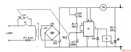
Work of the circuit
The disinfectant manufacturer circuit consists of power circuit, control circuit. (It is showed in picture 9-94.)
When you press button s 220V AC voltage will produce 5V DC voltage after being reduced, rectified and filtered by T, UR and CI. The voltage will separate into three parts. One is supplied to pole a, b and one lightens VL while another works as power of timing control circuit. If you increase the distance between pole a and pole b, the working current will decrease. (View)
View full Circuit Diagram | Comments | Reading(455)
Household appliances timing socket circuit
Published:2011/5/19 0:44:00 Author:TaoXi | Keyword: Household appliances, timing socket
Household appliances timing socket circuit (View)
View full Circuit Diagram | Comments | Reading(376)
Light control timing newspaper column light circuit
Published:2011/5/18 10:37:00 Author:TaoXi | Keyword: Light control, timing, newspaper column light
Light control timing newspaper column light circuit (View)
View full Circuit Diagram | Comments | Reading(389)
Light control timing advertising light circuit
Published:2011/5/18 10:34:00 Author:TaoXi | Keyword: Light control, timing, advertising light
Light control timing advertising light circuit (View)
View full Circuit Diagram | Comments | Reading(389)
Beijing Wuzhou elevator internal choice and floor indicating circuit
Published:2011/5/19 8:34:00 Author:TaoXi | Keyword: Beijing Wuzhou, elevator, internal choice, floor indicating
Beijing Wuzhou elevator internal choice and floor indicating circuit (View)
View full Circuit Diagram | Comments | Reading(348)
Beijing Wuzhou elevator power supply control circuit
Published:2011/5/19 8:35:00 Author:TaoXi | Keyword: Beijing Wuzhou, elevator, power supply, control circuit
Beijing Wuzhou elevator power supply control circuit (View)
View full Circuit Diagram | Comments | Reading(368)
Practical constant temperature controller circuit
Published:2011/5/13 0:59:00 Author:TaoXi | Keyword: Practical, constant temperature controller
Practical constant temperature controller circuit (View)
View full Circuit Diagram | Comments | Reading(400)
| Pages:1846/2234 At 2018411842184318441845184618471848184918501851185218531854185518561857185818591860Under 20 |
Circuit Categories
power supply circuit
Amplifier Circuit
Basic Circuit
LED and Light Circuit
Sensor Circuit
Signal Processing
Electrical Equipment Circuit
Control Circuit
Remote Control Circuit
A/D-D/A Converter Circuit
Audio Circuit
Measuring and Test Circuit
Communication Circuit
Computer-Related Circuit
555 Circuit
Automotive Circuit
Repairing Circuit