About SeekIC | Services | Payment | Advertisements service | Contact Us | Links
© 2008-2012 SeekIC.com Corp.All Rights Reserved.

Published:2011/5/16 5:00:00 Author:Sue | Keyword: Biochemical, Incubator, Controller
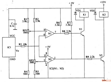
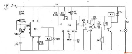
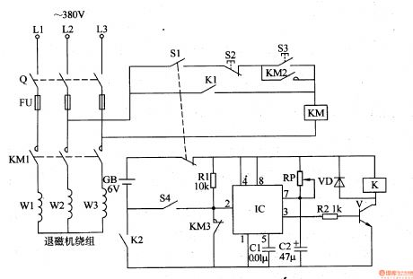
When the temperature is within the proper range, IC2's 2 pin's voltage is higher than that of 5 pin. 3 pin, 6 pin and 2 pin have the same voltage. 1 pin and 7 pin output low level, and k1, k2 are not connected. The cooling and heating circuits don't work.
When the temperature is higher than the set highest temperature, IC2's 3 pin's and 6 pin's voltage will be higher than that of 2 pin and 5 pin. IC2's 1 pin will have a high level instead of low level, making V2 connected and K2 connected. Its normally open contactor is connected, making the cooling system begin to work. When the temperature is lower than the set lowest temperature, IC2's 3 pin and 6 pin will have a lower voltage than 2 pin and 5 pin. IC2's 7 pin will have a high level,making V1 connected, and its normally open contactor is connected, making the heating circuit begin to work. (View)
View full Circuit Diagram | Comments | Reading(1083)
Published:2011/5/14 3:37:00 Author:Sue | Keyword: Soil Moisture, Tester
Working Principle:
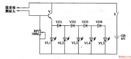
As seen in the figure 4-210,the soil moisture tester circuit consists of moisture detecting head, transistor V, diode VD1-VD4, LED VL1-VL5, potentiometer RP, power switch S and battery GB.
When the soil is too dry, V and VD1-VD4 are disconnected. VL1-VL5 then are not illuminated. When the soil deteced are moist, the water in the soil will make the resistance value between the 2 elektrodes of the detecting head become small, so V is connected and VL1-VL5 are illuminated one by one. The moister the soil is, the stronger breakover ability V will have, so the illuminated LED will be more. (View)
View full Circuit Diagram | Comments | Reading(2354)
Published:2011/5/16 3:24:00 Author:Sue | Keyword: Inverter
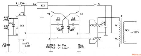
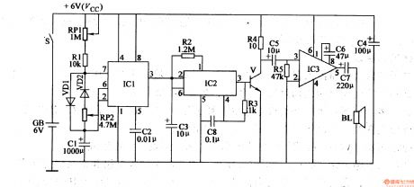
When S is connected, storage battery GB will provide monostable trigger circuit with a voltage of +12V, and another circuit will provide nonstable multivibrator circuit with +6V which is stablized by IC2.
When nonstable multivibrator begins to work, IC1's 3 pin will output oscillate pulse signal with a frequency of 100Hz, making V1 and V2 connected in turn. A and B will output high level flat pulse in turn, making VT1 and VT2 begin to work alternately, which can generate an alternating voltage of 5OHz、220V on T's secondary winding. (View)
View full Circuit Diagram | Comments | Reading(597)
Published:2011/5/16 3:46:00 Author:Sue | Keyword: Electronic, Mouse Killer
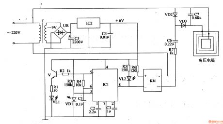
IC's 5 pin can output oscillator signal, which will drive VL1 to generate modulated infrared ray after the signal is amplified by V. When there is no mouse, VD1 receives no infrared ray, and IC1 will oscillate automatically, making 8 pin output high level. VL2 is not illuminated and KN and high voltage circuit don't work.
When there is mouse in the infrare ray detecting area, VD1 will receive the reflected infrared ray and turn 8 pin's high level into low level. VL2 is illuminatedand KN begins to work. High voltage will kill the mouse. When the mouse dies, the power is cut off, making VD1 stop working. IC1's 3 pin has no input signal, and 8 pin has high level. VL2 is not illuminated and the whole circuit stops working. (View)
View full Circuit Diagram | Comments | Reading(2494)
Published:2011/5/16 4:37:00 Author:Sue | Keyword: Electronic, Mouse Killer

When S is connected, 220V alternating voltage will generate 2KV high voltage,which will be sent to T's winding W2 after it is limited and changed by EL and T, and then the voltage will be sent to the high voltage electronic net through K. W3 will generate 3.5V alternating voltage, when HL is illuminated, the voltage can provide IC with working voltage after VD1-VD4's rectification and C1's filtering.
When the mouse touches the net, the high voltage current will kill the mouse. At the same time, K is connected, making IC begin to work and BL make a music warning sound, informing the users of the dead mouse. (View)
View full Circuit Diagram | Comments | Reading(1820)
Published:2011/5/16 4:21:00 Author:Sue | Keyword: Electronic, Mouse Killer

Working Principle:
As seen in the figure 4-193,this mouse killer circuit is simple. It consists of 5 times voltage rectifying circuit and labyrinth type poles.
When the 220V alternating voltage is rectified by VD1-VD5 and C1-C5, it will generate 1.5kV pulse high voltage on labyrinth type poles. When the mouse steps on it, the current will go through the mouse and kill it.
Component choices:
R: 1/2 W metal film resistor.
C1-C5: Ceramic capacitor with a withstand voltage of 600V.
VD1-VD5: 1N4007 silicon rectifying diode. (View)
View full Circuit Diagram | Comments | Reading(5096)
Published:2011/5/16 4:03:00 Author:Sue | Keyword: Electronic, Mouse Killer

When there is no mouse, IC1's output terminal will output high level. V1, high frequency oscillator, sound alarm circuit and high-voltage generator all don't work. When there is a mouse in the certain area, IC1's infrared ray will be reflected by the mouse and then receivedand processed by IC1, making IC1's output terminal have low level. Then V1 is connected and high frequency oscillator begins to work. IC2's 3 pin will output high frequency pulse signal,. which will generate 5kV pulse high voltage and kill the mouse. At the same time, V1 triggers the alarm circuit, driving BL make a warning sound. (View)
View full Circuit Diagram | Comments | Reading(2695)
Published:2011/5/17 5:38:00 Author:Sue | Keyword: Electronic, Mouse Exterminator
When S is connected, IC1’s 3 pin outputs high level, making the circuit begin to work. IC2’s 15 pin will output “meow” signal, which can drive BL to make a loud “meow” sound. Then V will work intermittently with the change of “meow” sound, and the bulbs will keep twinkling.
Then when IC1’s 6 pin’s voltage becomes higher than 2Vcc/3, IC1’s inside circuit reverses, making 3 pin have a low voltage, and K1 is released, which will stop the circuit. Then IC1’s 2 pin and 6 pin will have a lower voltage. When the voltage is lower than Vcc/3, K1 will be connected, and the circuit begins to work again. (View)
View full Circuit Diagram | Comments | Reading(631)
Published:2011/5/17 5:22:00 Author:Sue | Keyword: Electronic, Mouse Exterminator
When S is connected, IC1’s 2 pin and 6 pin have low level, and its 3 pin outputs high level, making IC2 begin to output meow electronic signal, which can drive BL to make a loud “meow”. At the same time, C1’s voltage becomes higher and higher. When IC1’s 2 pin and 6 pin have a voltage higher than 2Vcc/3, IC1’s 3 pin’s high level turns into low level, and BL stops the sound.
Then C1’s voltage becomes lower and lower. When the voltage reduces to Vcc/3, IC1’s 3 pin has a high level, driving BL to make a “meow” sound. (View)
View full Circuit Diagram | Comments | Reading(590)
Published:2011/5/20 2:52:00 Author:Felicity | Keyword: Car Windshield Wiper Controller (the 1st)
Work of the circuit
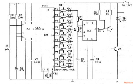
The circuit consists of One-shot trigger, Count divider, Multivibrator and motor driving circuit (It is showed in picture 7-163.).
Turn on power switch and +12V voltage supplies the working power. Press the button S1 for the first time windshield wiper motor turns over for 1s and then stops. Press the button for the second time the windshield wiper motor turns over for 2s and stops……Press the button for the tenth time the windshield wiper motor turns over for 10s and stops. (View)
View full Circuit Diagram | Comments | Reading(868)
Published:2011/5/22 7:11:00 Author:Felicity | Keyword: Eye-care Photometry Machine (the 3rd)
Work of the circuit
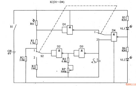
The circuit consists of LFO, light photometry circuit and LED indicating circuit (It is showed in picture 9-67.).
When the environmental light is too dim the value of RC is large. Here the red shining diode VL1 is lightened to remind the user to flip on the lamp. When the environmental light is suitable for reading and writing the value of RG is small. Here green shining diode VL2 is lightened. If the environmental light is too strong VL1 is lightened. (View)
View full Circuit Diagram | Comments | Reading(495)
Published:2011/5/22 7:10:00 Author:Felicity | Keyword: Eye-care Photometry Machine (the 2nd)
Work of the circuit
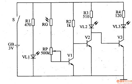
The circuit consists of power circuit, light photometry circuit and LED indicating circuit (It is showed in picture 9-66.).
Turn on the power switch S and VL1 is lightened. When the environmental light is suitable for reading and writing the value of RG is small. Here VL2 does not work while VL3 works. When the environmental light is not suitable for reading and writing the value of RG is increasing. Here VL2 starts to work while Vl3 stops. Change the value of RG to change the sensitivity of photometry. (View)
View full Circuit Diagram | Comments | Reading(455)
Published:2011/5/22 7:08:00 Author:Felicity | Keyword: Eye-care Photometry Machine (the 1st)
Work of the circuit
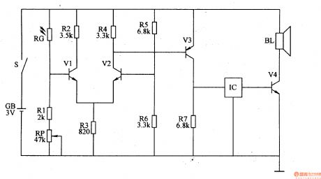
The circuit consists of photometry circuit, controlling circuit and music warning circuit (It is showed in picture 9-65.).
RG is a photometry element whose value decrease with the luminous heightening. When the environmental light is suitable for reading and writing the value of RG is small. Here IC and BL do not work. When the environmental light is not suitable for reading and writing the value of RG is increasing. Here IC works and BL makes music to remind the user to flip on the lamp. Change the value of RG to change the sensitivity of photometry.
(View)
View full Circuit Diagram | Comments | Reading(457)
Published:2011/5/22 7:06:00 Author:Felicity | Keyword: Eyesight Preserver (the 6th)
Work of the circuit
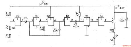
The circuit consists of controlled pulse OSC circuit, trigger controlling circuit, differential circuit, light examining circuit, reshaping circuit and shining driving circuit (It is showed in picture 9-64.).
When the interior light is strong enough the shining diode does not work. When the interior light is rather dim the controlled pulse amplifier starts to work and produces pulse signal. The signal drives shining diode to shine at a regular rate after being adjusted.
(View)
View full Circuit Diagram | Comments | Reading(443)
Published:2011/5/22 7:05:00 Author:Felicity | Keyword: Eyesight Preserver (the 5th)
Work of the circuit
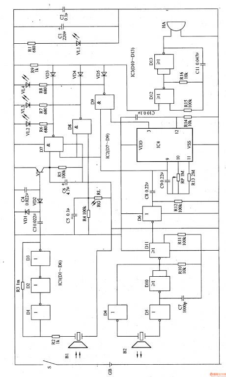
The circuit consists of timing circuit, trigger controlling circuit, light examining circuit, LED indicating circuit and sound warning circuit (It is showed in picture 9-63.).
When the environmental light is strong enough the voltage of VD is not so high. Here VL does not shine and HA makes no sound. When the environment light is dim t VL2A shines and HA makes sound to remind the user to flip on the lamp. When the regular time (30min) is reached, HA makes sound to remind the user to have a rest. If the user does not want to stop he can press button S2 to make the timer begin to work again. (View)
View full Circuit Diagram | Comments | Reading(426)
Published:2011/5/22 7:01:00 Author:Felicity | Keyword: Eyesight Preserver (the 4th)
Work of the circuit
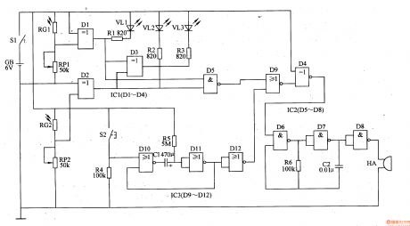
The circuit consists of power circuit, ultrasonic launching circuit, ultrasonic receiving circuit, timing controlling circuit, light examining circuit, LED indicating circuit and sound warning circuit (It is showed in picture 9-62.).
Turn on power switch and the circuit starts to work. When the user’s head is too near from the writing pad (the distance is less than 35cm) VL2 shines and HA makes the sound “tick tick” to alarm the user. When the environmental light is strong enough the voltage of VD is not so high. Here VL does not shine and HA makes no sound. When the environment light is dim the voltage of VD is high. Here VL shines and HA makes sound to remind the user to flip on the lamp. When the regular time is over VL3 is lightened and the HA makes sound to remind the user to have a rest. (View)
View full Circuit Diagram | Comments | Reading(450)
Published:2011/5/22 6:57:00 Author:Felicity | Keyword: Eyesight Preserver (the 2nd)
Work of the circuit
The circuit consists of power circuit, ultrasonic launching circuit, ultrasonic receiving circuit, timing controlling circuit, environment light examining circuit and acousto-optic warning circuit (It is showed in picture 9-60.).
Turn on power switch S and battery GB supplies 6V DC voltage to the whole circuit. When the user’s head is too near from the writing pad (the distance is less than 35cm) VL2 shines and HA makes the sound “tick tick” to alarm the user. When the regular time (45min) is over VL3 is lightened and the HA makes sound to remind the user to have a rest. (View)
View full Circuit Diagram | Comments | Reading(437)
Published:2011/5/22 9:32:00 Author:Felicity | Keyword: Eliminator of Visual Fatigue (the 2nd)
Work of the circuit
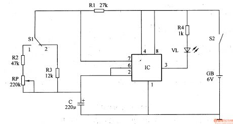
The circuit consists of shining diode V, resistor R1-R4, potentiometer RP, capacitor C, switch S1, S2 and battery GB (I t is showed in picture 9-58.).
When we use the machine we should put it exactly in front of our eyes (the distance should be about 25cm). We look at distance place and when VL shines (2s) our eyes will look at the shining point naturally. When VL stops shining (6s) we should look at the distance place again. In this way can we eliminate fatigue. (View)
View full Circuit Diagram | Comments | Reading(539)
Published:2011/5/22 9:30:00 Author:Felicity | Keyword: Eliminator of Visual Fatigue (the 1st)
Work of the circuit
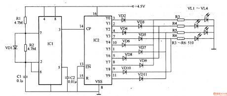
The circuit consists of pulse generator, counting frequency divisor and LED indicating circuit (It is showed in picture 9-57.).
Put four shining diode on the pad symmetrically and the distance between two diodes should be about 30mm. when the eyes are tired they will flex with the shining of the diodes. In this way can the user eliminates the visual fatigue. (View)
View full Circuit Diagram | Comments | Reading(514)
Published:2011/5/13 6:33:00 Author:Sue | Keyword: Automobile, Gears, Indicator
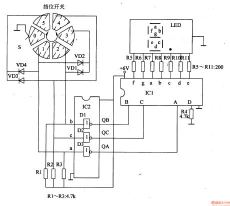
When the automobile is in neutral, S's 0 terminal is connected to the ground, the VD1-VD4 are disconnected. IC2's inside NOT gate D1-D3 output low level, and the LED indicator shows the number 0 .
When it's in gear 1, S's 1 terminal is connected to the ground, and NOT gate D3 will output high level. The indicator shows 1 .
When it's in gear 2, 2 terminal is connected to the ground, and NOT gate D1 will output high level. The indicator shows 2 .
When it's in gear 3, 3 terminal is connected to the ground, VD1 and VD2 are connected, NOT gate D1 and D3 will output high level. The indicator shows 3 .
When it's in gear 4, 4 terminal is connected to the ground, and NOT gate D2 will output high level. The indicator shows 4 .
When it's in gear 5, 5 terminal is connected to the ground, VD3 and VD4 are connected, NOT gate D2 and D3 will output high level. The indicator shows 5 . (View)
View full Circuit Diagram | Comments | Reading(1437)
| Pages:1843/2234 At 2018411842184318441845184618471848184918501851185218531854185518561857185818591860Under 20 |
Response in 12 hours
© 2008-2012 SeekIC.com Corp.All Rights Reserved.