
Circuit Diagram
Index 1849
using TWH9248 microwave to detect spotlight circuit
Published:2011/5/19 9:47:00 Author:Lena | Keyword: microwave, spotlight

(View)
View full Circuit Diagram | Comments | Reading(429)
sickroom wireless call system circuit
Published:2011/5/19 9:54:00 Author:Lena | Keyword: sickroom, wireless call system

sickroom wireless call system circuit:(a)emitter circuit;(b)receiving display circuit
(View)
View full Circuit Diagram | Comments | Reading(380)
JT-3WB type microwave burglar alarm circuit
Published:2011/5/19 9:45:00 Author:Lena | Keyword: microwave, burglar alarm

(View)
View full Circuit Diagram | Comments | Reading(378)
M18 machine core protection circuit
Published:2011/5/19 20:51:00 Author:Christina | Keyword: machine core, protection circuit

M18 machine core protection circuit:
(View)
View full Circuit Diagram | Comments | Reading(551)
The monostable trigger circuit composed of the 555
Published:2011/5/19 20:58:00 Author:Christina | Keyword: monostable trigger

The monostable trigger circuit composed of the 555 is as shown. Each function port is corresponding to this figure. The timing network is composed of the monostable trigger circuit, the resistance Ra and the capacitor C. (View)
View full Circuit Diagram | Comments | Reading(430)
PHILIPS 28GR6776 color TV power supply circuit
Published:2011/5/20 2:31:00 Author:Christina | Keyword: PHILIPS, color TV, power supply

The PHILIPS 28GR6776 color TV power supply circuit is as shown:
(View)
View full Circuit Diagram | Comments | Reading(7102)
Pulse delay generating circuit composed of the SN7490
Published:2011/5/19 20:19:00 Author:Christina | Keyword: Pulse delay generating
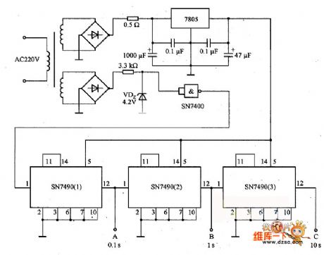
The pulse delay generating circuit composed of the SN7490 is as shown. It uses the 220V、50Hz AC as the standard delay pulse generating circuit. In the circuit, port A can output 0.1s delay pulse, port B can output 1s delay pulse, port C can output 10s delay pulse. This circuit is the standard pulse circuit and also the basic form circuit of the digital counter.
(View)
View full Circuit Diagram | Comments | Reading(1013)
refrigeration equipment temperature control circuit composed of the LM3911 monolithic temperature control integrated circuit
Published:2011/5/16 10:12:00 Author:Christina | Keyword: refrigeration equipment, temperature control, monolithic

The refrigeration equipment temperature control circuit composed of the LM3911 monolithic temperature control integrated circuit is as shown:
(View)
View full Circuit Diagram | Comments | Reading(870)
RAM extension method circuit of AVR
Published:2011/5/19 18:30:00 Author:Christina | Keyword: extension method, RAM

RAM extension method circuit of AVR is as shown:
(View)
View full Circuit Diagram | Comments | Reading(595)
The signal equipment circuit of VOLCANE-Citroen
Published:2011/5/19 20:35:00 Author:Borg | Keyword: signal equipment, VOLCANE-Citroen

The signal equipment circuit of VOLCANE-Citroen includes loudspeaker(20), steering signal lamps(488-491) and two suites of flashes, and all of them are under control of the flash relay(170), the steering lamp switch(part of the combination switch) controls the left-steering or right-steering signals. when the car run straight, the steer can cut off steering signal automatically.The danger alarm signal is delivered by the switch of 589, at the same time, the flash current is alternating its source, from F3(though igniting switch) to F6(battery fire wire of 30). (View)
View full Circuit Diagram | Comments | Reading(780)
Electronic Pest Repeller (2)
Published:2011/5/19 3:09:00 Author:Sue | Keyword: Electronic, Pest Repeller
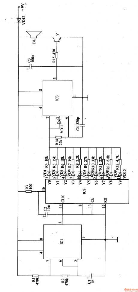
IC2 is a COMS decimal counter integrated circuit. It has 10 decoding output terminals(Y0-Y9). When it is working, its output terminals will output high level in turn. VD1-VD10 and R4-R13 will control IC3, generating 10 continuous frequency signals.
The audio output circuit consists of V and BL. IC3's 3 pin will output ultrasonic wave signal, which will emit ultrasonic wave through BL.
When the power is on, if BL can output audio signals with frequency that will change in every minute, then the circuit is working well. (View)
View full Circuit Diagram | Comments | Reading(793)
Electronic Mouse Exterminator (1)
Published:2011/5/17 5:13:00 Author:Sue | Keyword: Electronic, Mouse Exterminator (1)
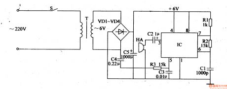
When S is connected, an alternating voltage of 220V will generate a direct current voltage of 6V after reduction, rectification and filtration. The 6V voltage will be sent to IC's 4 pin and 8 pin, making the oscillator begin to work.
The 50Hz alternating current signal of T will be sent to IC's 5 pin through C4, R3, controlling the oscillator. IC's 3 pin will output 20-40kHz varied sweep frequency signals, which will be sent to HA through C2, forcing HAto generate some sound pressure to drive the mouse away. (View)
View full Circuit Diagram | Comments | Reading(760)
Electronic Mouse Exterminator (3)
Published:2011/5/17 5:31:00 Author:Sue | Keyword: Electronic, Mouse Exterminator
When the power is connected, the astable multivibrator begins to work. IC1’s 7 pin will output 11Hz oscillator signal. After the signal is transformed into sawtooth wave by V, it will output 18-30kHz sweep frequency signal from IC2’s 4 pin after IC2’s control and process. The signal will force HA to emit ultrasonic beam of 100dB after TWH68’s amplification and boost. The ultrasonic beam can then drive awaymice or pests in a certain area. (View)
View full Circuit Diagram | Comments | Reading(419)
The ECM plug voltage circuit of Daewoo-ESPERO
Published:2011/5/18 22:45:00 Author:Borg | Keyword: ECM, voltage circuit, Daewoo-ESPERO
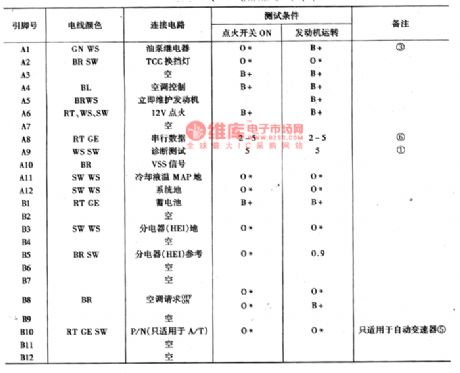
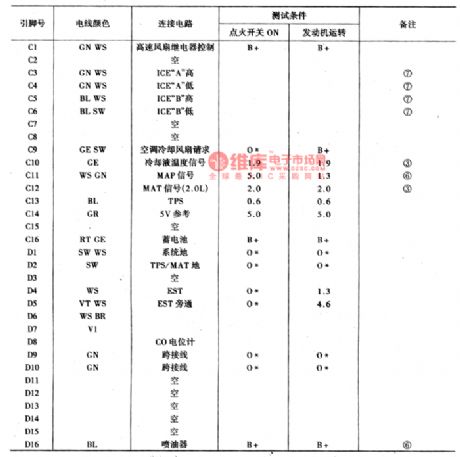
Before the test is done, there are some conditions to conform:①the engine reaches the normally working temperature; ② the test pin has not connected with the ground.Instructions of marked notes are shown in 13-4.B+: system voltage; *:voltage lower than 0.5v; ▽:voltage lower than 1v; ① the pulse voltage that changes with front drive wheel, it ranges from 0.6v to battery voltage; ②the voltage is 12V in the starting 2S; ③voltage changes with temperature; ⑤the system voltage when the transmission is at the heading or back-up gear; ⑥the changing voltage; ⑦the changing A.C voltage. (View)
View full Circuit Diagram | Comments | Reading(1047)
AN7105-The integrated reproducing circuit of single door stereo
Published:2011/5/19 1:06:00 Author:Borg | Keyword: integrated reproducing circuit, single door stereo


1.the internal circuit and pin functions of AN7105AN7105 consists of two lines of pre-amplifiers and balancers, and its pin functions and data are listed in Table 1.
2.the typical application circuit of AN7105
The typical application circuit of AN7105 is as shown in Figure 1.
3.signal courseMagnetic head signals come in from pins of (11) and ⑧, after magnifying and frequency compensation, they come out from (13) and ⑥, then they come in through (15) and ④ after the volume is magnified. Finally, the signals are output from (15) and ④, and the headphone is driven to generate sound. (View)
View full Circuit Diagram | Comments | Reading(1207)
Electronic Sterilizer (the 1st)
Published:2011/5/19 8:20:00 Author:Felicity | Keyword: Electronic Sterilizer (the 1st),
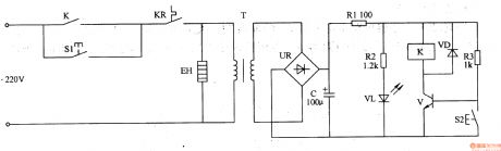
Work of the circuit
The electronic sterilizer circuit consists of power circuit, control circuit. (It is showed in picture 9-96.)Process circuit and press SI. 220V AC voltage supplies 12V direct-current working voltage after being reduced, rectified, filtered, bucked and limited by T, UR, C and RI. The voltage makes V conducted and lightens VL in the meantime. If you want to stop heating in the process of heating and sterilizing you can press S2 and cut off the machine’s power. (View)
View full Circuit Diagram | Comments | Reading(546)
AN7085N5-the integrated recording circuit of single door
Published:2011/5/19 6:01:00 Author:Borg | Keyword: integrated recording circuit, single door


AN7085N5 is an integrated recording circuit of single door, which is produced by Panasonic. It is used in low voltage radios and the same kind of stereo systems.1.The internal circuit and pin functions of AN7085N5AN7085N5 contains sub-circuits of pre-amplifier, recording drive, recording/reproducing transmission, power amplifier,ACL and mute power amplifier,etc.The IC is in 20-lead dual line plastic package,and its pin functions and data are listed in Table 1.
Table 1 pin functions and data of AN7085N52.the typical application circuit of AN7085N5
(View)
View full Circuit Diagram | Comments | Reading(486)
AN7081K-the integrated reproducing circuit of single door stereo
Published:2011/5/19 6:07:00 Author:Borg | Keyword: integrated reproducing circuit, single door


1.the function feature of AN7081K(1)there is a motor-steady circuit(equal to AV6550), so one chip can fulfill all the functions of a common radio. It is convenient to use, while the earlier two generations need a outer motor-steady circuit.(2)The 6 resistances in both right and left channels of the preset balance amplifier circuit are fixed in the IC, so 6 outer resistances are not necessary any more.(3)The output GL capacitor (220μF), shock eliminating capacitor(0.033μF) and negative feedback capacitor(1OμF) of power amplifier stage are removed, so 6 capacitors in total are saved.
(View)
View full Circuit Diagram | Comments | Reading(1029)
AN7060-The integrated circuit of preset audio motivation
Published:2011/5/19 6:12:00 Author:Borg | Keyword: integrated circuit, preset audio motivation


AN7060 is an integrated circuit of preset audio motivation produced by Panasonic, which is used in HI-FI stereos.1.the internal circuit and pin functions of AN7060AN7060 is an integrated circuit of high-pressure-proof preset audio, which is used to motivate a power amplifier of 60w, and it characterizes with low noise and litter distortion. The IC is in 9-lead single line package, whose internal circuit is as shown in Figure 1, and its pin functions and data are listed in Table 1.
Figure 1 the internal circuit of AN7060
Figure 1 the internal circuit of AN7060
(View)
View full Circuit Diagram | Comments | Reading(4701)
AN7108-the integrated reproducing circuit of single door stereo
Published:2011/5/18 8:35:00 Author:Borg | Keyword: reproducing circuit, single door stereo


AN7108 is in 16-lead dual in-line package, which is formed by two same channels, and each channel consists of preamplifier, volume control and headphone drive power amplifier circuit. The V ref wave filter and bias circuit in the circuit have good ripple contain factors, and they can normally work without any adjustment. Besides, just a potentiometer could control the electric pressure controlled stereo volume, and it overcomes the frictions noise, the pressure controlled amplifier consists of drives.
(View)
View full Circuit Diagram | Comments | Reading(815)
| Pages:1849/2234 At 2018411842184318441845184618471848184918501851185218531854185518561857185818591860Under 20 |
Circuit Categories
power supply circuit
Amplifier Circuit
Basic Circuit
LED and Light Circuit
Sensor Circuit
Signal Processing
Electrical Equipment Circuit
Control Circuit
Remote Control Circuit
A/D-D/A Converter Circuit
Audio Circuit
Measuring and Test Circuit
Communication Circuit
Computer-Related Circuit
555 Circuit
Automotive Circuit
Repairing Circuit