
Circuit Diagram
Index 1850
AN6663S-the integrated drive circuit of zooming motors
Published:2011/5/19 6:28:00 Author:Borg | Keyword: drive circuit, zooming motors


AN6663S is an integrated drive circuit of zooming motors produced by Panasonic, which is widely used in all kinds of NV camcorders of Panasonic.AN6663S is used in Panasonic NV一M9000 as the typical applicaiton circuit, see as Figure 1. The IC is in 8-lead dual in-line package, and its pin functions and data are listed in Table 1.
Figure 1 the typical application circuit of AN66635
Table 1 pin functions and data of AN663S (View)
View full Circuit Diagram | Comments | Reading(697)
The servo driven circuit of AN8389SE1
Published:2011/5/18 20:28:00 Author:Borg | Keyword: servo driven


AN8389SE1 is an integrated single door circuit of laser head servo driver produced by Panasonic, which is widely used in VCD,SVCK,CVD and DVD players.1.the internal circuitAN8389SE1 contains a 4-channel BTL drive circuit, which can directly convert digital servo control signals into the drive output of servo executing parts. The internal circuit of it is shown in Figure 1.
Figure 1. The internal circuit of AN8389SE12.Pin functionsPin functions of AN8389SE1 are listed in Table 1.
(View)
View full Circuit Diagram | Comments | Reading(746)
The diagnosis circuit of Daewoo ESPERO fault code of 14
Published:2011/5/18 1:54:00 Author:Borg | Keyword: diagnosis circuit, Daewoo ESPERO
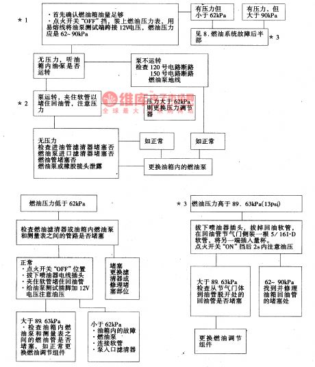

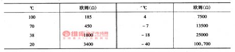
The code of 14 means that that the signal voltage of coolant temperature sensor is low--indicating high temperature(see as Figure 4 and Figure 16). The coolant temperature sensor controls the ECM signal with a thermistor. Firstly , ECM imposes a voltage on the sensor in No.410 circuit, when the engine becomes cool, the resistance of the sensor(thermistor) is getting high, then ECM will detect a high signal voltage. When the engine is getting hotter, the resistance of the sensor is becoming low, the voltage is coming down. When at the normal engine temperature, the ECM pin of C10 will get the voltage of 1.5~2.0V.
(View)
View full Circuit Diagram | Comments | Reading(1004)
wide range timing switch circuit
Published:2011/5/19 1:20:00 Author:TaoXi | Keyword: wide range, timing switch

The wide range timing switch circuit
This circuit uses the monolithic time transmitter circuit XR2242, the timing range is from few milliseconds to few days. This circuit is composed of a time-based oscillator, a 8-bit binary counter and a control trigger. The time-base circuit is composed of the resistor R and capacitor C, there are three kinds of output pulse time: T=RC (pin 8), T=2RC (pins 2) and T=128RC (pin 3). Through the additional voltage, we can make the output automatic reset. By using the positive edge of the trigger input port pulse, we can start the time process.
(View)
View full Circuit Diagram | Comments | Reading(727)
The new generation touch stepless light and speed adjustment circuit NB7232
Published:2011/5/18 3:47:00 Author:TaoXi | Keyword: new generation, touch, stepless, light and speed adjustment
Related components PDF download:
NB7232
The basic working principle of the circuit (dimming example): the human body electricity and the city electricity have the same frequency, when the human body touches the touch tablet, the body electricity becomes the standard MOS electrical level with the wave cutting, the amplification and the reshaping of the input buffer stage. When the touch duration is more than 32ms and less than 332ms, the logic control part circuit is in the switching working state. When the touch duration is more than 332ms, the logic control part circuit is in the dimmer working state, the output trigger pulse phase angle continuous cyclical changes between the 41 degrees to 159 degrees, and according to the human eye sensibility, there are three processes: the fast process, the slow process and the intermittent process.
(View)
View full Circuit Diagram | Comments | Reading(661)
The air-bag and seatbelt control circuit of Buick-Century
Published:2011/5/18 2:31:00 Author:Borg | Keyword: air-bag, seatbelt, control circuit, Buick-Century
The air-bag is a kind of negative protection equipment, when the car is crashing with others in the running way, the sensor receives an impact signal, as long as it reaches a supposed degree, the sensor will generate a signal and send it to the controller, then the electric controller will compare it with the saved data. If it reaches the condition of opening the air-bag, the drive circuit will send a starting signal to the air generator of the air-bag module, and the generator will explode the gas-forming admixture and swell the air-bag.
(View)
View full Circuit Diagram | Comments | Reading(595)
The light, signal and starting wiring circuit of DPCA-VOLCANE DC7140 ZX(2)
Published:2011/5/19 20:02:00 Author:Borg | Keyword: wiring circuit, DPCA-VOLCANE

Only when the light switch(211) is at the 2 gear, can the head lights of 786 and 787(low beam), and fog light of 484 and 485 be connected, besides the fog lights are controlled by the 588 switch(see as the figure).
211-left combination switch; 300-igniting switch; 310,311-left-right front door lamp switch;314-back up lamp switch; 319-brake lamp switch; 492,493-left-front and right-front position lamp; 496,497-left-rear and right-rear position lamp; 498,499-left-right back-up lamp; 504,505-left and right brake lamps; 786,787-left-and-right front headlights; 806-head fog light relay (View)
View full Circuit Diagram | Comments | Reading(585)
The ground connections of Buick-Century (see Figure 1,2,3)
Published:2011/5/18 3:22:00 Author:Borg | Keyword: ground connections, Buick-Century
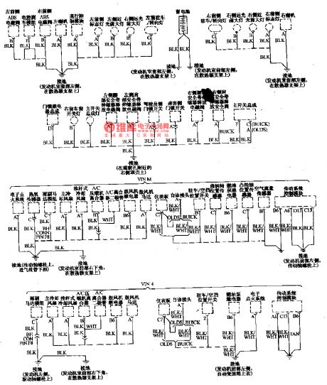
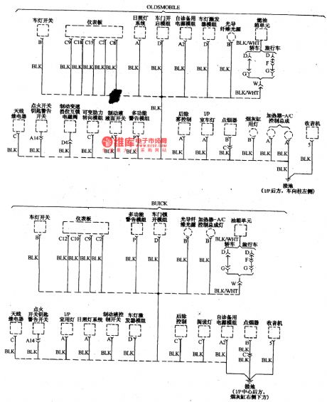
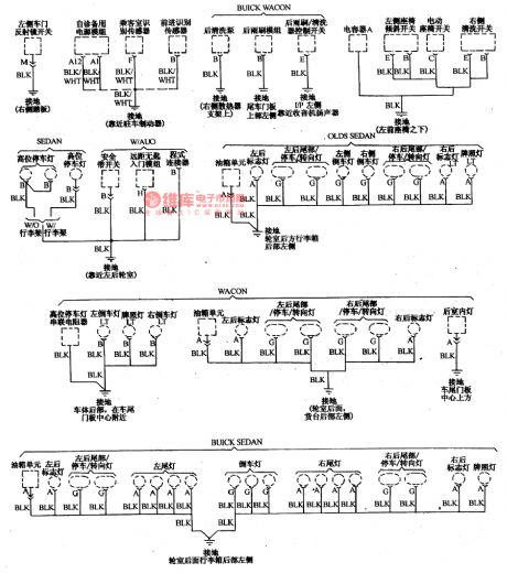
These years, it is the common point of importing car circuits to explicitly describe the ground connections of electric equipment, as the car electric equipment is fixed throughout the car, and many general parts are fixed on metal slides and shaking engines or brackets, so its not dependable to connect in a single line. It is necessary to link all the ground connections into a reliable net with the negative point of the battery, which is also convenient to detect partial faults. The following shows the chief ground connections:
The ground connections of Buick-Century (1)
(View)
View full Circuit Diagram | Comments | Reading(852)
The electric control circuit if Buick-Century engine and auto transmission(2)
Published:2011/5/18 20:01:00 Author:Borg | Keyword: control circuit, Buick-Century

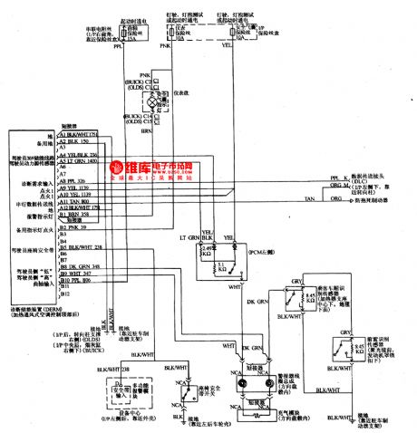
The control system PCM(a) of Buick-Century engine(3.1L)The notes of terminal No. And wire colors are clear, and the wires are also marked with No., which is convenient to check, for example, the No. of fault indicator wire is 419, brown/white stripe, which is linked to the No.1 terminal of connector C. The colors of other wires are as follows. BLK一black LTGRN一light green DKGRN一dark green TAN一tan BLU一blue ORG一orange GRN一green VlO一violet BRN一brown PNK一pink GRY一grey WHT一white CLR一clear (View)
View full Circuit Diagram | Comments | Reading(1357)
Household appliances electricity utilization timer circuit
Published:2011/5/19 0:43:00 Author:TaoXi | Keyword: Household appliances, electricity utilization, timer
The Household appliances electricity utilization timer circuit (View)
View full Circuit Diagram | Comments | Reading(466)
AN6650-the integrated motor speed-stable circuit
Published:2011/5/19 6:50:00 Author:Borg | Keyword: integrated, speed-stable


AN6650 is an integrated motor speed-stable circuit produced by Panasonic, which is use to control the speed of the reproducing motor.1.The internal circuit and pin functions of AN6650The internal circuit of AN650 is as shown in Figure 1, and it contains sub-circuits, such as reference voltage circuit, comparing circuit and starting circuit, etc. The IC is in 8-lead dual in-line package, and its pin functions and data are listed in Table 1.
2.the typical application circuit of AN66635The typical application circuit of AN66635 is as shown in Figure 1.
3.working process (View)
View full Circuit Diagram | Comments | Reading(6480)
transformer oscillator circuit
Published:2011/5/19 19:36:00 Author:John | Keyword: transformer, oscillator
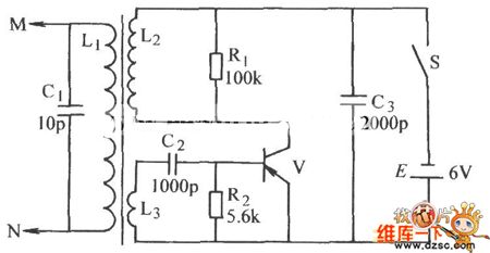
Transformer oscillator circuit is shown below.
(View)
View full Circuit Diagram | Comments | Reading(906)
AN6612/S-the integrated circuit of DC motor speed-stable control
Published:2011/5/19 7:16:00 Author:Borg | Keyword: integrated circuit, DC motor, speed-stable


1.the internal circuit and pin functions of AN6612/SThe internal circuit of AN6612/S is shown in Figure 1(b), and the IC contains sub-circuits of voltage comparator, reference voltage forming, combination regulator, current source and starter, etc.
Figure 1 the internal circuit and outline pin arrangement of AN6612/S
AN6612/S is in flat 8-lead dual in-line plastic package, whose outline pin arrangement are as shown in Figure 1(a). Its pin functions and data are listed in Table 1.2. The main electric parameters of AN6612/S
(View)
View full Circuit Diagram | Comments | Reading(1865)
Mini contactless temperature box circuit
Published:2011/5/13 0:53:00 Author:TaoXi | Keyword: Mini, contactless, temperature box
Mini contactless temperature box circuit (View)
View full Circuit Diagram | Comments | Reading(401)
Toshiba CV60 elevator safety loop circuit
Published:2011/5/19 8:51:00 Author:TaoXi | Keyword: Toshiba, elevator, safety loop
Toshiba CV60 elevator safety loop circuit (View)
View full Circuit Diagram | Comments | Reading(939)
Active half-frequency circuit
Published:2011/5/19 19:53:00 Author:Christina | Keyword: Active, half-frequency
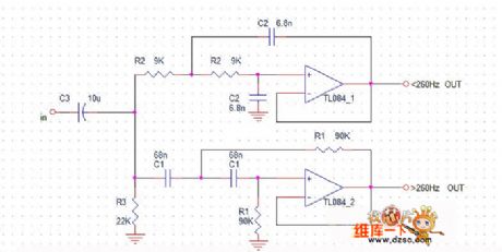
The crossover point of the active half-frequency circuit is 260Hz, the figure shows only one sound channel, the other sound channel is the same, the op-amp IC can select a 4-channel op-amp TL084 (voltage: 7V-36V), or the op-amp IC can select two NE5532 (10-30V), JRC4850(4-32V).
(View)
View full Circuit Diagram | Comments | Reading(1403)
Toshiba CV-180 elevator frequency modulation door opening circuit (2)
Published:2011/5/19 9:06:00 Author:TaoXi | Keyword: Toshiba, elevator, frequency modulation, door opening circuit
Toshiba CV-180 elevator frequency modulation door opening circuit (2) (View)
View full Circuit Diagram | Comments | Reading(433)
8051 SCM basic working circuit
Published:2011/5/19 19:46:00 Author:Christina | Keyword: SCM, basic working circuit
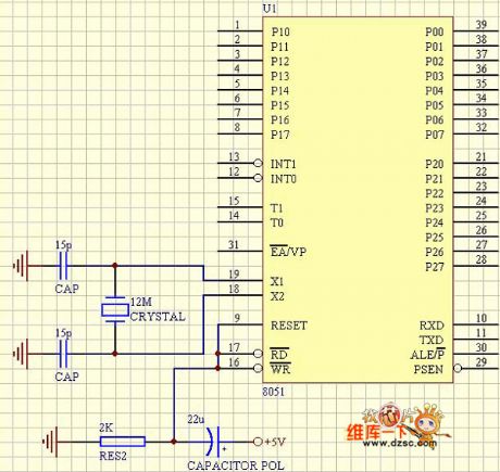
8051 SCM basic working circuit
(View)
View full Circuit Diagram | Comments | Reading(1165)
Typical low-pass filter circuit
Published:2011/5/19 19:43:00 Author:Christina | Keyword: Typical, low-pass filter

The Typical low-pass filter circuit:
(View)
View full Circuit Diagram | Comments | Reading(526)
Toshiba CV60 elevator DC door opening circuit
Published:2011/5/19 8:52:00 Author:TaoXi | Keyword: Toshiba, elevator, DC, door opening
Toshiba CV60 elevator DC door opening circuit (View)
View full Circuit Diagram | Comments | Reading(505)
| Pages:1850/2234 At 2018411842184318441845184618471848184918501851185218531854185518561857185818591860Under 20 |
Circuit Categories
power supply circuit
Amplifier Circuit
Basic Circuit
LED and Light Circuit
Sensor Circuit
Signal Processing
Electrical Equipment Circuit
Control Circuit
Remote Control Circuit
A/D-D/A Converter Circuit
Audio Circuit
Measuring and Test Circuit
Communication Circuit
Computer-Related Circuit
555 Circuit
Automotive Circuit
Repairing Circuit