
Circuit Diagram
Index 1851
Toshiba CVl80 elevator safety loop circuit
Published:2011/5/19 8:44:00 Author:TaoXi | Keyword: Toshiba, elevator, safety loop
Toshiba CVl80 elevator safety loop circuit (View)
View full Circuit Diagram | Comments | Reading(422)
The e-glass elevating and control door lock wiring circuit of DPCA-VOLCANE DC7140
Published:2011/5/19 10:11:00 Author:Borg | Keyword: door lock, wiring circuit, DPCA-VOLCANE
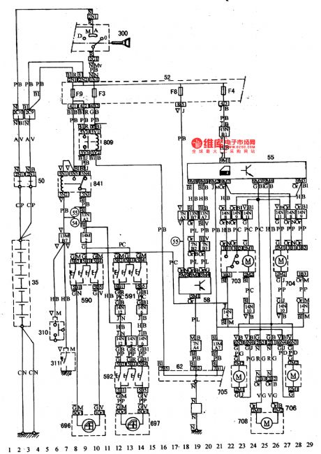
See as the figure: the e-glass elevating and control door lock wiring circuit of DPCA-VOLCANE DC714035-battery; 50-power supply box; 52-inscribing fuse box; 55-controller of the centralized control lock; 58-e-control components; 62-ground connection box; 300-igniting switch; 310-left-front lamp switch; 311-right-front lamp switch; 590,591,592-glass elevation motor switch; 696,697-glass elevation motor; 703,704,705,706 and 708-door lock motor; 809-glass elevating relay; 841-glass elevating motor relay (View)
View full Circuit Diagram | Comments | Reading(829)
Liquid drip automatic heating alarm circuit
Published:2011/5/13 0:52:00 Author:TaoXi | Keyword: Liquid drip, automatic heating, alarm circuit
Liquid drip automatic heating alarm circuit (View)
View full Circuit Diagram | Comments | Reading(482)
Single Power And Low Power Consumption Instrument Amplifier Circuit Composed Of INA102
Published:2011/5/19 9:40:00 Author:Robert | Keyword: Single Power, Low Power Consumption, Instrument Amplifier

The single power and low power consumption instrument amplifier circuit is shown in the picture below. This circuit uses the low power consumption instrument integrated amplifier INA102, whose internal resistance has excellent temperature performance and working stability. There are two 100kΩ resistance in the picture making up a voltage divider (to divide the power voltage). It makes the out-phase input port have a 4.5V DC voltage. So when there is no input signal its output voltage is still DC 4.5V. Its voltage magnification times would be 100 according to the circuit connection in the picture.
(View)
View full Circuit Diagram | Comments | Reading(656)
Toshiba CV60 (7.5 kW) elevator main circuit
Published:2011/5/19 8:54:00 Author:TaoXi | Keyword: Toshiba, elevator, main circuit
Toshiba CV60 (7.5 kW) elevator main circuit (View)
View full Circuit Diagram | Comments | Reading(529)
Toshiba CV180 elevator band-type braking circuit
Published:2011/5/19 9:11:00 Author:TaoXi | Keyword: Toshiba, elevator, band-type braking circuit
Toshiba CV180 elevator band-type braking circuit (View)
View full Circuit Diagram | Comments | Reading(390)
Toshiba CV-180 elevator frequency modulation door opening circuit (1)
Published:2011/5/19 9:07:00 Author:TaoXi | Keyword: Toshiba, elevator, frequency modulation, door opening circuit
Toshiba CV-180 elevator frequency modulation door opening circuit (1) (View)
View full Circuit Diagram | Comments | Reading(339)
Toshiba CV180 elevator main circuit
Published:2011/5/19 8:56:00 Author:TaoXi | Keyword: Toshiba, elevator, main circuit
Toshiba CV180 elevator main circuit (View)
View full Circuit Diagram | Comments | Reading(545)
Flash lamp SCR trigger circuit
Published:2011/5/19 19:17:00 Author:Christina | Keyword: Flash lamp, SCR, trigger

This circuit can provide protection for camera synchronous contacts, if we use the GE4JL8B instead of the SRC, this circuit can be used as the auxiliary flash.
(View)
View full Circuit Diagram | Comments | Reading(1214)
Precise Isolation Instrument Amplifier (INA102) Circuit
Published:2011/5/19 9:57:00 Author:Robert | Keyword: Precise, Isolation, Instrument, Amplifier

The precise isolation instrument amplifiercircuit is shown in the picture below. From the picture, this circuit's first stage uses the gain-variable instrument amplifier INA102, Andthe back stage can usea isolation amplifier such as coupled linear amplifier ISO100 or 3650. Also it can usethe transformer coupled isolation amplifier 3656. Its power supply uses 722 type isolation power.
(View)
View full Circuit Diagram | Comments | Reading(514)
Toshiba CV180 elevator control power supply circuit
Published:2011/5/19 9:00:00 Author:TaoXi | Keyword: Toshiba, elevator, control power supply
Toshiba CV180 elevator control power supply circuit (View)
View full Circuit Diagram | Comments | Reading(397)
High-Precision High-Impedance Instrument Amplifier Circuit Composed Of OPA2111
Published:2011/5/19 7:42:00 Author:Robert | Keyword: High-Precision, High-Impedance, Instrument, Amplifier

The High-Precision High-Impedance Instrument Amplifier Circuit Composed Of OPA2111 is shown in the picture. The circuit in the picture's total voltage magnification times is Av=10×(1+2R2/R1)=1000 times. The back stage uses a differential amplifier circuit whose gain is 10. This would expand the instrument amplifier's input common-mode voltage range tobe ±10V.
(View)
View full Circuit Diagram | Comments | Reading(648)
Police car sound and light analog circuit
Published:2011/5/19 19:02:00 Author:Christina | Keyword: Police car, sound, light, analog circuit

This circuit can sends out the sound of police car, meanwhile the signal parade is flashing, you can install it in the police car and fire truck models to increase the enjoyment of the toys.
In this circuit, the multivibrator oscillation circuit is composed of BG1 and BG2, the direct coupling amplifier is composed of the BG5 and BG6 to provide enough signal voltage for signal lamps.
(View)
View full Circuit Diagram | Comments | Reading(1288)
Randomness electronic small toys circuit
Published:2011/5/19 18:56:00 Author:Christina | Keyword: Randomness, electronic small toys
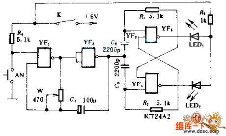
This toys circuit can be played by two or more people. Before you press AN, open the circuit, LED1 and LED2 will shine alternately; if you press AN2, there is only one LED alternately shines. If LED1 shining means one person gets 1 point, LED2 shining means one person loses 1 point, so we can ensure who is the winner according to the number of points.
(View)
View full Circuit Diagram | Comments | Reading(718)
XTR108 Three-Wire RTD Connection Circuit
Published:2011/5/19 18:07:00 Author:Robert | Keyword: Three-Wire, RTD, Connection

The XTR108 three-wire RTD connection circuit is shown in the picture shown below. It may cause errors by connecting RTD sensor lead resistance. Using the 1 and 2 connection method in the picture, the lead resistances would be the same if 1 and 2 have the same lead length to XTR108. And the caused disturbance size and direction also are the same. This disturbance is common-mode voltage. The common-mode voltage ca be limited by the XTR108's PGA. This circuit has 5 optional temperature range by choosing R21~R25 to choose 5 different minimum temperature features.
(View)
View full Circuit Diagram | Comments | Reading(1186)
The light and signal circuit of DPCA-VOLCANE DC7140 ZX
Published:2011/5/19 19:48:00 Author:Borg | Keyword: light and signal circuit, DPCA-VOLCANE
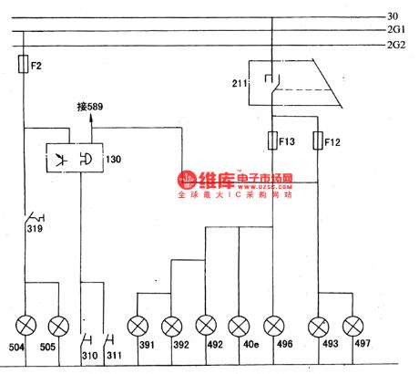
The transmission between high and low beams is fulfilled by pulling the handling behind.
The lighting and signal circuit of DPCA-VOLCANE DC7140 ZX40e-position indicator; 130-alarm for not-off light; 211-left combination switch; 310,311-left-right front door lamp switch; 319-brake lamp switch; 391.392-left and right license lamp; 492,493-left-front and right-front position lamp; 496,497-left-rear and right-rear position lamp; 504,505-left and right brake lamp; 589-danger alarm lamp switch. (View)
View full Circuit Diagram | Comments | Reading(497)
Simple Pulse Signal Generator Circuit Composed Of 74LS221
Published:2011/5/19 7:49:00 Author:Robert | Keyword: Simple, Pulse Signal, Generator

The Simple Pulse Signal Generator Circuit Composed Of 74LS221is shown in the picture. This signal generator mainly uses two TTL integrated circuit 74LS221 to generate the t=4us pulse signals. The components used is less, so it is easy to debug and maintain.
(View)
View full Circuit Diagram | Comments | Reading(2313)
XTR110 Voltage-Current Converter Circuit
Published:2011/5/19 17:45:00 Author:Robert | Keyword: Voltage-Current Converter

As shown in the picture, when the output current exceeds 40mA the internal resistance 50Ω in the XTR110 (R9) should be replaced by external resistance REXT. REXT is connected between the 13 foot and 16 foot. REXY=R9(original span/required span). For example, the XTR110 in the picture's original span is 20mA and now the required span is 10A. If R9=50Ω, then the REXT=R9=50X(20/10000)=0.1Ω.
(View)
View full Circuit Diagram | Comments | Reading(3285)
The stereo system circuit of DPCA-VOLCANE DC714OZX
Published:2011/5/19 11:16:00 Author:Borg | Keyword: stereo system, DPCA-VOLCANE
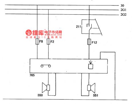

The left and right loudspeakers are controlled by the left combination switch, when the igniting switch is at A gear and M gear, then the radio can be used(see as Figure a and b).
Figure a. The principle stereo circuit of DPCA-VOLCANE DC714OZX211-left combination switch; 550,551-left and right loudspeakers; Fl-FI3-fuse box
Figure b. The stereo system wiring circuit of DPCA-VOLCANE DC714OZX35-battery; 50-power supply box; 52-inscribing fuse box; 62-ground connection box; 211-left combination switch; 300-igniting switch; 550,551-left and right loudspeakers; 765-radio (View)
View full Circuit Diagram | Comments | Reading(554)
The room light, cigarette lighter and clock principle circuits of DPCA-VOLCANE DC714OZX
Published:2011/5/19 11:55:00 Author:Borg | Keyword: room light, cigarette lighter, principle circuit, DPCA-VOLCANE
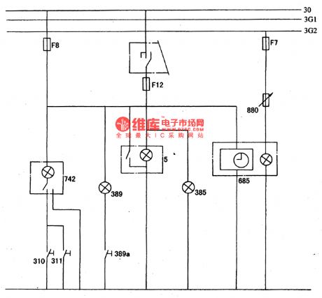

The fuse of F8 links with the battery fire wire, and it controls the room light(742), trunk(389), cigarette lighter and clock(685). The room light can be shut down by hand switch, or controlled by switches of 310 and 311(see as Figure a and b).
Figure a. The room light, cigarette lighter and clock principle circuits of DPCA-VOLCANE DC714OZX5-cigarette lighter; 310,311-the left and right front door switches; 385-ashtray light; 389-trunk light; 389a-trunk light switch; 685-digital clock; 742-head ceiling light; 880-instrument lamp.
(View)
View full Circuit Diagram | Comments | Reading(585)
| Pages:1851/2234 At 2018411842184318441845184618471848184918501851185218531854185518561857185818591860Under 20 |
Circuit Categories
power supply circuit
Amplifier Circuit
Basic Circuit
LED and Light Circuit
Sensor Circuit
Signal Processing
Electrical Equipment Circuit
Control Circuit
Remote Control Circuit
A/D-D/A Converter Circuit
Audio Circuit
Measuring and Test Circuit
Communication Circuit
Computer-Related Circuit
555 Circuit
Automotive Circuit
Repairing Circuit