power supply circuit
The stereo system circuit of DPCA-VOLCANE DC714OZX
Published:2011/5/19 11:16:00 Author:Borg | Keyword: stereo system, DPCA-VOLCANE | From:SeekIC


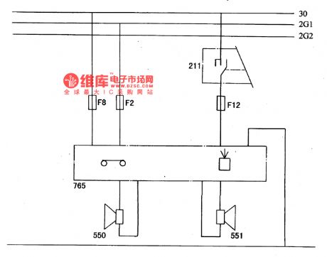
The left and right loudspeakers are controlled by the left combination switch, when the igniting switch is at A gear and M gear, then the radio can be used(see as Figure a and b).
Figure a. The principle stereo circuit of DPCA-VOLCANE DC714OZX211-left combination switch; 550,551-left and right loudspeakers; Fl-FI3-fuse box
Figure b. The stereo system wiring circuit of DPCA-VOLCANE DC714OZX35-battery; 50-power supply box; 52-inscribing fuse box; 62-ground connection box; 211-left combination switch; 300-igniting switch; 550,551-left and right loudspeakers; 765-radio
Reprinted Url Of This Article:
http://www.seekic.com/circuit_diagram/Power_Supply_Circuit/The_stereo_system_circuit_of_DPCA_VOLCANE_DC714OZX.html
Print this Page | Comments | Reading(3)

Article Categories
power supply circuit
Amplifier Circuit
Basic Circuit
LED and Light Circuit
Sensor Circuit
Signal Processing
Electrical Equipment Circuit
Control Circuit
Remote Control Circuit
A/D-D/A Converter Circuit
Audio Circuit
Measuring and Test Circuit
Communication Circuit
Computer-Related Circuit
555 Circuit
Automotive Circuit
Repairing Circuit
Code: