
Circuit Diagram
Index 1856
The fault detection circuit of Daewoo ESPERO air-conditioner compressor control
Published:2011/5/16 21:41:00 Author:Borg | Keyword: fault detection circuit, Daewoo ESPERO, air-conditioner

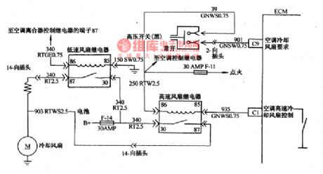
To make sure that engine will run stable when air-conditioner is work at the idling speed, and to lighten the load of the engine when accelerating(the throttle is open), the air-conditioning circuit is cut off. Daewoo ESPERO is installed with computer ECM control air-conditioner compressor and electric fans of condensers(see as Figure 26 and Figure 7).
This circuit consists of low-voltage switch, high-switch, air-conditioner power supply relay, air-conditioner clutch and compressor electromagnetic clutch.
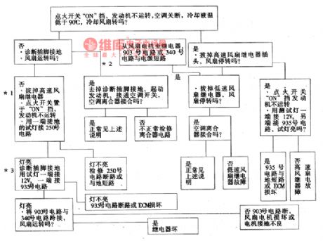
The detection course of cooling fan control circuit is as follows:
(View)
View full Circuit Diagram | Comments | Reading(1455)
The parking and neutral gear switch circuit fault detection circuit of Daewoo ESPERO
Published:2011/5/16 21:57:00 Author:Borg | Keyword: parking gear, neutral gear, detection circuit
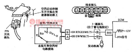
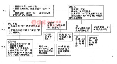
Parking/neutral(P/N) gear switch touch spot is part of the neutral staring switch, which is fixed in auto transmission drive bridge. When the car is at neutral gear(N) or parking(P) gear, the touch spot is closed; when the car is at geared state(R,D,L), the switch is cut off(see as Figure 25). The computer ECM imposes a igniting switch voltage on No.434 line through a current-limiting resistance, when voltage on the line is lower than 1V, then ECM will decide the switch is closed.
(View)
View full Circuit Diagram | Comments | Reading(820)
BA3529BF-the integrated reproducing circuit of single door stereo
Published:2011/5/14 8:22:00 Author:Borg | Keyword: reproducing circuit, single door stereo


BA3529BFis an integrated reproducing circuit of single door stereo produced by ROHM Corp., Japan, which is often used in Aiwa walk-man.1.main parameterspower supply voltage range:1.8-6V, typical voltage:3V.Maximum power: 750mW.Stereo spread:45dB.Output power of each channel:when the power supply voltage is 3V, RL=16Ω,THD=10%, the Po is 34mA。2.the internal circuitBA3529BF contains all the circuits that stereo radios need: 2-channel preamplifier, 2-channel power amplifier, mute circuit and electronic speed-stable circuit.
(View)
View full Circuit Diagram | Comments | Reading(455)
BA3828-the integrated circuit of electrical channel-selecting presetting
Published:2011/5/14 3:23:00 Author:Borg | Keyword: integrated circuit, channel-selecting

BA3828 is an integrated circuit of electrical channel-selecting presetting produced by Toyo Corp.,Japan, which is widely used in domestic stereos, car stereo and all kinds of high-class walk-man systems.BA3828 contains tuning power supply circuits, channel-selecting presetting circuits, FM presetting switch circuits, channel-selecting tuning voltage circuits, LED driven control circuit and other additional function circuits. The IC is in 22-lead dual in-line package, whose pin functions and data are listed in Table 1.
(View)
View full Circuit Diagram | Comments | Reading(653)
D17156CU-an integrated microcomputer circuit of single door
Published:2011/5/13 21:15:00 Author:Borg | Keyword: microcomputer circuit, single door


D17156CU is an integrated microcomputer circuit of single door, which is widely used in Fushibao cookers.1.function featuresD17156CU is used in Fushibao RZ-UTl8Y cookers produced by Hitachi Corp., Japan, whose typical application circuit is as shown in Figure 1-1. The chip can fulfill indefinite intelligent control of volumetric heating from buttom, ceiling and side.2.Pin functions and dataD17156CU is in 28-lead dual in-line package, whose pin functions and instructions are in Table 1-1. Table 1-1 pin functions and instructions of single door computer D17156CU
(View)
View full Circuit Diagram | Comments | Reading(619)
The fault codes of 8A-FE engine control system
Published:2011/5/13 9:26:00 Author:Borg | Keyword: fault codes, control system
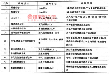
The fault codes of 8A-FE engine control system are listed in Table2.
Table 2. the codes of 8A-FE engine control system
(View)
View full Circuit Diagram | Comments | Reading(553)
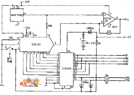
put 0~10V into 4 ~ 20MA voltage-current conversion circuit
Published:2011/5/11 21:53:00 Author:Fiona | Keyword: voltage-current conversion


Circuit Work
OP amplifier A2 for the constant current output circuit, current sense resistor R11 produces a voltage at 0.4 ~ 2.0V. A2's input consists of two parts: 0.4V the home side and the input signal, when there is no signal, in order to make the offset is 0.4V, because R3 = 10R4, the VR2 's output voltage must be -4V. Since A2 bias is-0.4V,the A2 input signal must be 0 ~ 1.6V, the two parts together is equivalent to-0.04V ~ 2.0V. Increase the sensitive voltage to make the OP amplifier A1 as attenuator, and its magnification is 0.16.
Component selection
(View)
View full Circuit Diagram | Comments | Reading(3241)
Multifunction Charger Three
Published:2011/5/18 10:15:00 Author:Michel | Keyword: Multifunction Charger Three
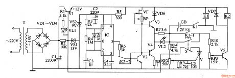
The Multifunction charger introduced in the example can charge nickel-spread and nickel-hydroge batteries.Before charging,the charger discharges batteries and switches into constant current charging.During charging,there is a heavy load current and batteries cut off charge circuit wnen they are fully charged automatically to avoid excessive charging.Ciruit's Work PrincipleThis multifunction charger is composed of power supply circuit, impulsator,charging circuit,discharging circuit and control circuit.Power supply circuit consists of mains transformer,T,commutation diode,VDl-VD4,filter capacitors,C1and C2,line regulation tube,V1,voltage regulator diodes,VS1 and VS2,resistors,R1,R2 and R5 and LED,VL1 and it is showed as the picture 5-65. (View)
View full Circuit Diagram | Comments | Reading(709)
Millivoltmeter circuit
Published:2011/5/18 19:28:00 Author:John | Keyword: Millivoltmeter

Millivoltmeter circuit is shown below.
(View)
View full Circuit Diagram | Comments | Reading(2072)
Digital voltmeter circuit
Published:2011/5/18 19:30:00 Author:John | Keyword: Digital voltmeter
Digital voltmeter circuit is shown below.
(View)
View full Circuit Diagram | Comments | Reading(8)
Water Level Indicator (3)
Published:2011/5/17 20:41:00 Author:Sue | Keyword: Water Level, Indicator

When water level is lower than L, VL1-VL3 are not illuminated.
When the level reaches L, V1 will have a high level, making VL1 illuminated, indicating that the level has reached 1/3.
When water level reaches M, VL2 is illuminated.
When the level reaches H,VL3 is illuminated, indicating the water case is full. At the same time, audio oscillator begins to work, forcing BL to make a warning sound to inform the users. (View)
View full Circuit Diagram | Comments | Reading(2374)
TA8256HV31.5 supper bass processing integrated circuit
Published:2011/5/11 5:23:00 Author:chopper | Keyword: supper bass processing, integrated circuit
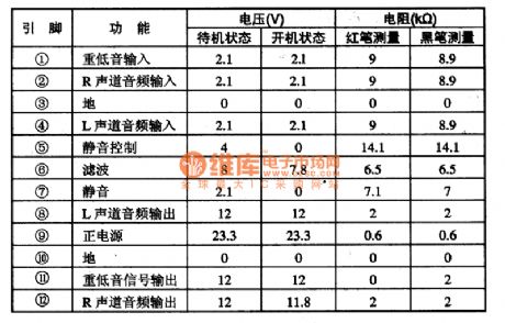
TA8256HV31.5 is a new audio signal amplification integrated circuit manufactured by Toshiba.It is applied to audio device and new large-screen color TV.1.Functional characteristicsIn the TA8256HV31.5 integrated circuit there are three audio processing circuits with the same function and audio signal.Two of them process the sound channel signal of R,L;the other one processes supper bass signal.2.Function and data of pinsTA8256HV31.5 integrated circuit is applied to Changhong CN-l5 chipset color TVs,its function and data of pins of the integrated circuit is shown as following table 1.
(View)
View full Circuit Diagram | Comments | Reading(424)
Water Level Indicator (2)
Published:2011/5/17 20:38:00 Author:Sue | Keyword: Water Level, Indicator

When there is no water, VL1-VL4 are not illuminated.
When water level reaches 1/4, IC’s 13 pin will have a high level, which will make S1 connected. VL1 is illuminated. As water level becomes higher, VL2-VL4 will be illuminated one by one.
When the water case is full, IC’s 12 pin will have a high level, which will make VM illuminated. S will be connected and forces HA to make a warning sound. (View)
View full Circuit Diagram | Comments | Reading(3281)
Water Level Indicator (1)
Published:2011/5/17 20:34:00 Author:Sue | Keyword: Water Level, Indicator

When there is no water, N1-N4’s reverse input terminal will have a voltage which is higher than +5V base voltage, so N1-N4 will output low level, and VL1-VL4 are not illuminated.
When water level reaches D, N1’s reverse input terminal’s voltage will be lower than +5V, N1 outputs high level and illuminates VL4, indicating that water level reaches D.
As the water level becomes higher, N2,N3,N4 outputs high level one by one, and VL3,VL2,VL1 is illuminated one by one.
When VL1-VL4 are all illuminated, users will turn off the suction pump. (View)
View full Circuit Diagram | Comments | Reading(3665)
Eyesight Protection Timer Circuit Composed of 555
Published:2011/5/17 5:41:00 Author:Joyce | Keyword: Eyesight Protection, Timer, Composed of 555

As shown in the figure is the eyesight protection timing circuit. This circuit uses 555 , R2, R3, R4 and C3 to constitute a pulser of variable duty ratio, which will control the bi-direction thyristor VS to make the desk lamp illume at a certain time and put out for a short time ,in order to ensure that the readers` eyes could get rest while reading to protect their eyesight.The desk lamp will put out for 10 minutes every 50 minutes.
(View)
View full Circuit Diagram | Comments | Reading(523)
Simple Long Timer Circuit Composed of 555
Published:2011/5/17 5:33:00 Author:Joyce | Keyword: Simple , Long Timer, Composed of 555

As shown in the figure is the simple long timer circuit .Start timing by pressing the switch AN, and you can regulate PR to adjust the time span,which ranges from 3 minutes to 220 minutes. If the capacitance C is changed to 2200μF,the time range will be 40 minutes to 48 hours. feet③ of 555 outputs timing control signals . If you use this circuit to control higher power, you have to connect a relay between end B and C or end A and B.You should use relay contacts to control all kinds of timing loads. (View)
View full Circuit Diagram | Comments | Reading(807)
Common Electrical Motor Controlled Circuit (1)
Published:2011/5/13 5:42:00 Author:Sue | Keyword: Common, Electrical Motor, Controlled
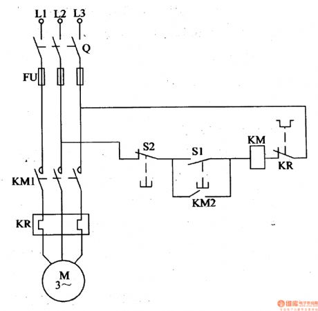
Working Principle: As seen in the figure 4-111, the circuit consists of switch Q, fuse FU, ac contactor KM, start button S1, stop button S2 and thermal relay KR. When we start the circuit, we should connect the switch Q, and push the start button S1. Then KM is connected, which make KM1 and KM2 connected, and the motor M begins to work. When S1 is disconnected, KM is still connected because of KM2's effect. When we stop the circuit, we should push the stop button S2, and KM is disconnected, which make KM1 and KM2 disconnected, and M stops working. (View)
View full Circuit Diagram | Comments | Reading(4407)
Common Electrical Motor Controlled Circuit (2)
Published:2011/5/13 5:41:00 Author:Sue | Keyword: Common, Electrical Motor, Controlled

Working Principle:
As seen in the figure 4-112, the button controlled motor circuit consists of knife switch Q, fuse FU, ac contactor KM, thermal relay KR, intermediate relay KA1,KA2 and control button S.
When we start the circuit, we should connect the knife switch Q, and push S to connect KA1, which will connect KA1-1 and KA13. The normally closed interlock KA1-2 is disconnected, which makes normally opened main interlock KM1 and assist interlock KM3,KM4 connected, and M begins to work. When S is released, KA is disconnected, and KM is still connected under the action of KM4.
When we stop the circuit, push S, and KA2 is connected, normally opened interlock KA2-2 is connected, while normally closed interlock KA2-1 and KA2-3 are disconnected, which makes KM released, then M stops working. (View)
View full Circuit Diagram | Comments | Reading(3891)
Alternating Current Contactor Energy-Saving Circuit
Published:2011/5/17 5:48:00 Author:Sue | Keyword: Alternating Current, Contactor, Energy-Saving
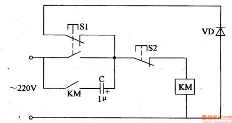
When the power is connected and S1 is pushed, 220V voltage will be sent to AC contactor KM’s coil, and make KM connected. Then C begins to charge. When S1 is released, C’s charging current makes KM remain connected, and VD will be connected to KM by S1 S2. Then the alternating current power will charge C in positive half period while discharge C in negative half period. KM will remain connected. (View)
View full Circuit Diagram | Comments | Reading(595)
Water Level Detector
Published:2011/5/14 3:48:00 Author:Sue | Keyword: Water Level, Detector

When the water doesn't reach the certain water level, the water level sensor doesn't work. A voltage of +9V will be provided to VD1, making IC's 13,10,1,4 pins have high level, and the alarm circuit doesn't work.
When the water reach the certain level, the sensor begins to work, making VD1's positive pole have low level, and VD1 becomes disconnected. Then the blocking oscillator begins to work, and IC's 10 pin outputs the oscillate signal with a long peried. When the signal voltage is positive, VD2 is connected, IC's 1 pin has high level, and the audio oscillator doesn't work. When the voltage is negative, VD2 is disconnected, and the oscillator begins to work. So the oscillator will work under the control of the blocking oscillator, and IC's 6 pin will output interrupted signals which will promote BL to make a warning sound. (View)
View full Circuit Diagram | Comments | Reading(1685)
| Pages:1856/2234 At 2018411842184318441845184618471848184918501851185218531854185518561857185818591860Under 20 |
Circuit Categories
power supply circuit
Amplifier Circuit
Basic Circuit
LED and Light Circuit
Sensor Circuit
Signal Processing
Electrical Equipment Circuit
Control Circuit
Remote Control Circuit
A/D-D/A Converter Circuit
Audio Circuit
Measuring and Test Circuit
Communication Circuit
Computer-Related Circuit
555 Circuit
Automotive Circuit
Repairing Circuit