power supply circuit
Common Electrical Motor Controlled Circuit (1)
Published:2011/5/13 5:42:00 Author:Sue | Keyword: Common, Electrical Motor, Controlled | From:SeekIC

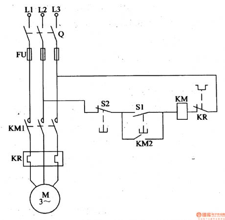
Working Principle: As seen in the figure 4-111, the circuit consists of switch Q, fuse FU, ac contactor KM, start button S1, stop button S2 and thermal relay KR. When we start the circuit, we should connect the switch Q, and push the start button S1. Then KM is connected, which make KM1 and KM2 connected, and the motor M begins to work. When S1 is disconnected, KM is still connected because of KM2's effect. When we stop the circuit, we should push the stop button S2, and KM is disconnected, which make KM1 and KM2 disconnected, and M stops working.
Reprinted Url Of This Article:
http://www.seekic.com/circuit_diagram/Power_Supply_Circuit/Common_Electrical_Motor_Controlled_Circuit_1.html
Print this Page | Comments | Reading(3)

Article Categories
power supply circuit
Amplifier Circuit
Basic Circuit
LED and Light Circuit
Sensor Circuit
Signal Processing
Electrical Equipment Circuit
Control Circuit
Remote Control Circuit
A/D-D/A Converter Circuit
Audio Circuit
Measuring and Test Circuit
Communication Circuit
Computer-Related Circuit
555 Circuit
Automotive Circuit
Repairing Circuit
Code: