
Circuit Diagram
Index 1853
The fault code diagram of Santana 2000GLi
Published:2011/5/16 4:27:00 Author:Borg | Keyword: fault code, Santana
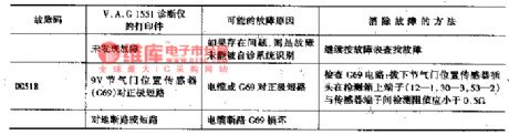
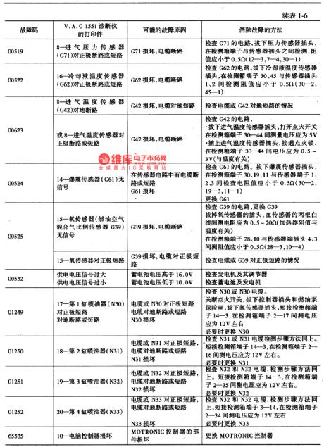
Fault codes are represented by 5 bit numbers. Before switching the shown faulted components, we should check if the wires and connected tightly, especially for sporadic faults(sp). The fault codes are listed in Table 1, in the table, detection box is corresponding to computer connecting terminals.
(View)
View full Circuit Diagram | Comments | Reading(556)
The control system self-detection circuit of 2000GLi engine
Published:2011/5/16 11:08:00 Author:Borg | Keyword: control system, Santana


V.A.G1551 fault diagnosis equipment can not only do test on the electric spray engines of Red Flag, Jetta, Golf and Passat, but also can do the job to the engines of Santana. The car should have these conditions if we want use the equipment: the would be detected engines must have been run for a needed time, the coolant temperature need to be more than 7℃, batteries are normal, fuses are good and the ground connection of the engine is OK.
1-steer; 2-VACI551 fault diagnosis equipment; 3-the power supply plug of the equipment; 4-the outlet of the equipment.
(View)
View full Circuit Diagram | Comments | Reading(718)
BA3406AL-the integrated dual preamplifier reproducing circuit
Published:2011/5/15 5:04:00 Author:Borg | Keyword: preamplifier, reproducing circuit


BA3406AL is an integrated dual preamplifier reproducing circuit produced by Toyo Power Tool Corp., Japan, which is used in recorders and music centers.the internal circuit and pin functions of BA3406AL1.The internal circuit of BA3406AL consists of two lines of pre-amplifiers, mute circuits and metal strap compensate circuits of same functions. Whose internal circuit and pin functions are shown in Figure 1.
Figure 1 internal circuit and pin functions of BA3406AL2.Typical application circuit of BA3406ALThe working voltage of BA3406AL ranges 6-14V, typical application voltage is 8V.
(View)
View full Circuit Diagram | Comments | Reading(1430)
Transceiver module which is composed of the remote control voice doorbell RCMlA/RCMlB
Published:2011/5/11 3:03:00 Author:TaoXi | Keyword: Transceiver module, remote control, voice doorbell
The remote control doorbell saves the wiring between the button and the doorbell, the installation position of the doorbell is very flexible and it is convenient. The voice integrated circuit can use the KD15 series of soft packaging integrated circuit. After the circuit is installed, you can use it immediately. when you are using it, you should make the receiver away from the big metal objects to avoid the influencing of the remote sensitivity. (View)
View full Circuit Diagram | Comments | Reading(539)
Twelve-channel wireless remote control circuit TH9738
Published:2011/5/11 19:54:00 Author:TaoXi | Keyword: Twelve-channel, wireless remote control
The key components datathat will be used in this artical:
TH9738 CD4514 78L05 9014 (View)
View full Circuit Diagram | Comments | Reading(710)
Digital paging systems F36-F and F36-J
Published:2011/5/11 19:20:00 Author:TaoXi | Keyword: Digital paging system
The transmission circuit:
The receiving circuit: (View)
View full Circuit Diagram | Comments | Reading(618)
Pyroelectric infrared sensing socket analog sound circuit BISS0001
Published:2011/5/11 19:03:00 Author:TaoXi | Keyword: Pyroelectric, infrared sensing socket, analog sound
The circuit is as shown. It is composed of the pyroelectric infrared sensor, the infrared signal processing circuit, the relay control socket circuit, the analog sound circuit and the AC step-down rectifier circuit.etc. When someone walked into the pyroelectric infrared monitoring field, the socket gets the electricity, its electrical equipments start running; meanwhile, the analog sound circuit sends out the voice to remind the equipment master. (View)
View full Circuit Diagram | Comments | Reading(616)
Pyroelectric infrared sensing automatic door control and voice calling circuit HN911D
Published:2011/5/11 19:03:00 Author:TaoXi | Keyword: Pyroelectric, infrared sensing, automatic door control, voice calling
The circuit is as shown. It is composed of the pyroelectric infrared sensor module, the delay control network, the electric coupling & SCR control circuit, the language voice circuit, the AC step-down rectifier circuit.etc. The HN911D is one kind of pyroelectric infrared detector module. (View)
View full Circuit Diagram | Comments | Reading(833)
Motor electronic governor controller 6
Published:2011/5/17 21:18:00 Author:Nicole | Keyword: Motor, electronic governor controller

The circuit work theory
This motor electronic governor controller circuit is composed of power supply circuit, ultralow-frequency oscillator and control implement circuit, the circuit is shown in the figure 8-63.
The power supply circuit is made of depressurization capacitor C3, bleeder resistor R1, rectifier diodes VD3, filter capacitors C1 and steady voltage diode VS.
The ultralow-frequency oscillator consists of time base integrated circuit IC, resistors R2-R4, potentiometers RP, capacitor C2 and diodes VD1, VD2.
The control implement circuit is composed of solid state relay KN(SSR)、transistor VT and resistor R6.
(View)
View full Circuit Diagram | Comments | Reading(1679)
Agricultural Products Automatic Drying Case
Published:2011/5/17 6:07:00 Author:Sue | Keyword: Agricultural Products, Automatic, Drying Case

After the drying case begin to work, RS’s resistance value becomes smaller, and IC2’s 4 pin’s voltage becomes higher, making the oscillator begin to work. IC2’s 3 pin outputs high level, illuminating VL3, and M begins to drive the steam out of the case. When C4’s voltage reaches 6.7V, 3 pin outputs low level and M stops working. Then C4’s voltage becomes lower, illuminating VL3 again, and M begins to work. When the it is not too wet, IC’2 will stop working. When it is too wet, IC2 works again. So the circuit works like this until the product is dry and VL3 is not illuminated. (View)
View full Circuit Diagram | Comments | Reading(553)
Over-voltage over-current protector
Published:2011/5/18 4:24:00 Author:TaoXi | Keyword: Over-voltage, over-current, protector

In the normal working hours, Tr1 and Tr2 are cut-off, 555 is reset, and the discharge transistor of the 555 is conducted, it absorbs the current from Tr3's base electrode to make Tr3 saturated, the 5~12V power directly sends to the main load. When the load absorbs too much current, Rsc's pressure drop increases, the Tr1 conducts and 555 is triggered, so the internal discharge transistor cuts off, then the Tr3. At this time, the 555 is in the single stable state, when the single stable time is up, as long as the load over-flow phenomena is not ruled out, 555 will be triggered again, Tr3 will continue separate the load.
(View)
View full Circuit Diagram | Comments | Reading(872)
General timing controller circuit
Published:2011/5/18 3:56:00 Author:TaoXi | Keyword: General, timing, controller
General timing controller circuit (View)
View full Circuit Diagram | Comments | Reading(643)
Excellent performance city electricity over-voltage protection circuit
Published:2011/5/18 3:13:00 Author:TaoXi | Keyword: Excellent performance, city electricity, over-voltage protection

The circuit is as shown, this circuit uses the capacitance step-down and simple manostat circuit, when the power supply voltage is normal, the TL431C control pole voltage is less than 2.5V, TL431C circuit is not conduction, the relay contact point is not close. When the city electricity voltage is 250V, the rectifier & filtering current is 3.3mA, the voltage drop of R3 is 11V and the voltage drop of the diode and regulator tube (including the glowing tube) are 26V and 37V. The voltage is separated by R1 and R2, point A's voltage is 2.55V, the TL431C circuit is conduction, and relay K closes, the city electricity becomes the short-circuit to make the power supply current flowing device tripping or the fuse fusing, so this circuit protects the household appliances.
(View)
View full Circuit Diagram | Comments | Reading(1684)
Washing machine electronic timer circuit
Published:2011/5/17 21:50:00 Author:TaoXi | Keyword: Washing machine, electronic timer
Washing machine electronic timer circuit (View)
View full Circuit Diagram | Comments | Reading(693)
Time adjustable timer circuit
Published:2011/5/17 21:49:00 Author:TaoXi | Keyword: Time, adjustable, timer
Time adjustable timer circuit (View)
View full Circuit Diagram | Comments | Reading(657)
Practical double-watch timing circuit (4)
Published:2011/5/17 22:03:00 Author:TaoXi | Keyword: Practical, double-watch, timing circuit

Related components PDF download:
9014
The circuit principle is as shown. After the process of buck, rectifier, filtering, this circuit supplies the working power supply to the control circuit. The bi-stable circuit is composed of the BG1 and BG2 and other external components, they work in the switching state. The control switch is composed of the BG3 and the relay to control the output of the AC 220V voltage. Both of the digital watches have the functions of point timekeeping and music button, they connect to the control circuit by using their two voice signal output line. Electronic watch 2 responsible for open, when it outputs the music electrical signal, the circuit cuts off BG2 by C6 and D7, at this time BG1 conducts to maintain this state. (View)
View full Circuit Diagram | Comments | Reading(993)
Double-watch timer circuit (2)
Published:2011/5/17 20:35:00 Author:TaoXi | Keyword: Double-watch, timer circuit

AC220V is reduced by the transformer B and is full-wave rectified by the diode D1 and D2, then is filtered by the capacitance C, so we get the 14V DC voltage, this voltage can be added to the both ends of the SCR1, when the watch A outputs a timing alarm clock pulse (open), SCR1 is conducted, relay J1 gets the electricity and it's contact-point J1 closes, timing socket has the electricity to output, meanwhile J1-1's contact-point closes to make the preparation for SCR2 conduction, when the time is up,watch B outputs a timing alarm clock pulse (close), SCR2 is conducted, it's contact-point J2 cuts off, SCR1 cuts off too, also it's contact-points J1 and J1-1. Timing socket has no electricity to output. J2 recovers the closing state.
(View)
View full Circuit Diagram | Comments | Reading(907)
Gas water heater optical coupling self-control exhaust fan circuit
Published:2011/5/17 9:31:00 Author:TaoXi | Keyword: Gas water heater, optical coupling, self-control, exhaust fan
The Gas water heater optical coupling self-control exhaust fan circuit is as shown: (View)
View full Circuit Diagram | Comments | Reading(448)
three-phase motor overheating fault phase protection circuit
Published:2011/5/17 9:20:00 Author:TaoXi | Keyword: three-phase, motor, overheating, fault phase, protection circuit
The three-phase motor overheating fault phase protection circuit is as shown: (View)
View full Circuit Diagram | Comments | Reading(569)
Double-bit temperature controller circuit
Published:2011/5/17 9:13:00 Author:TaoXi | Keyword: Double-bit, temperature controller

This circuit's temperature measuring bridge is connected to the thermistor, the bridge diagonal is connected to the two-stage amplifier which is composed of the complementary transistor, the output port is connected to the relay coil. The emitter current of the output transistor gets through the 10Ω resistance of the bridge's right branch to form the positive feedback to gain the switching characteristic and the hysteresis. Select the appropriate feedback resistor values (0 to 100Ω), you can get the 0 to 3% wide hysteresis.
(View)
View full Circuit Diagram | Comments | Reading(435)
| Pages:1853/2234 At 2018411842184318441845184618471848184918501851185218531854185518561857185818591860Under 20 |
Circuit Categories
power supply circuit
Amplifier Circuit
Basic Circuit
LED and Light Circuit
Sensor Circuit
Signal Processing
Electrical Equipment Circuit
Control Circuit
Remote Control Circuit
A/D-D/A Converter Circuit
Audio Circuit
Measuring and Test Circuit
Communication Circuit
Computer-Related Circuit
555 Circuit
Automotive Circuit
Repairing Circuit