Automotive Circuit
Soil Moisture Tester
Published:2011/5/14 3:37:00 Author:Sue | Keyword: Soil Moisture, Tester | From:SeekIC

Working Principle:
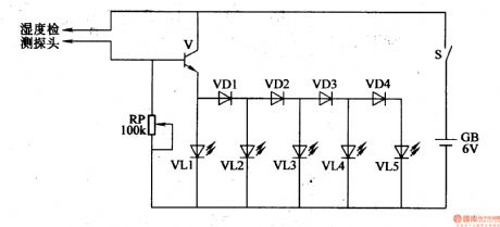
As seen in the figure 4-210,the soil moisture tester circuit consists of moisture detecting head, transistor V, diode VD1-VD4, LED VL1-VL5, potentiometer RP, power switch S and battery GB.
When the soil is too dry, V and VD1-VD4 are disconnected. VL1-VL5 then are not illuminated. When the soil deteced are moist, the water in the soil will make the resistance value between the 2 elektrodes of the detecting head become small, so V is connected and VL1-VL5 are illuminated one by one. The moister the soil is, the stronger breakover ability V will have, so the illuminated LED will be more.
Reprinted Url Of This Article:
http://www.seekic.com/circuit_diagram/Automotive_Circuit/Soil_Moisture_Tester.html
Print this Page | Comments | Reading(3)

Article Categories
power supply circuit
Amplifier Circuit
Basic Circuit
LED and Light Circuit
Sensor Circuit
Signal Processing
Electrical Equipment Circuit
Control Circuit
Remote Control Circuit
A/D-D/A Converter Circuit
Audio Circuit
Measuring and Test Circuit
Communication Circuit
Computer-Related Circuit
555 Circuit
Automotive Circuit
Repairing Circuit
Code: