Automotive Circuit
Inverter (1)
Published:2011/5/16 3:24:00 Author:Sue | Keyword: Inverter | From:SeekIC

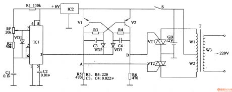
When S is connected, storage battery GB will provide monostable trigger circuit with a voltage of +12V, and another circuit will provide nonstable multivibrator circuit with +6V which is stablized by IC2.
When nonstable multivibrator begins to work, IC1's 3 pin will output oscillate pulse signal with a frequency of 100Hz, making V1 and V2 connected in turn. A and B will output high level flat pulse in turn, making VT1 and VT2 begin to work alternately, which can generate an alternating voltage of 5OHz、220V on T's secondary winding.
Reprinted Url Of This Article:
http://www.seekic.com/circuit_diagram/Automotive_Circuit/Inverter_1.html
Print this Page | Comments | Reading(3)

Article Categories
power supply circuit
Amplifier Circuit
Basic Circuit
LED and Light Circuit
Sensor Circuit
Signal Processing
Electrical Equipment Circuit
Control Circuit
Remote Control Circuit
A/D-D/A Converter Circuit
Audio Circuit
Measuring and Test Circuit
Communication Circuit
Computer-Related Circuit
555 Circuit
Automotive Circuit
Repairing Circuit
Code: