Automotive Circuit
Electronic Mouse Exterminator (4)
Published:2011/5/17 5:38:00 Author:Sue | Keyword: Electronic, Mouse Exterminator | From:SeekIC

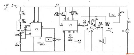
When S is connected, IC1’s 3 pin outputs high level, making the circuit begin to work. IC2’s 15 pin will output “meow” signal, which can drive BL to make a loud “meow” sound. Then V will work intermittently with the change of “meow” sound, and the bulbs will keep twinkling.
Then when IC1’s 6 pin’s voltage becomes higher than 2Vcc/3, IC1’s inside circuit reverses, making 3 pin have a low voltage, and K1 is released, which will stop the circuit. Then IC1’s 2 pin and 6 pin will have a lower voltage. When the voltage is lower than Vcc/3, K1 will be connected, and the circuit begins to work again.
Reprinted Url Of This Article:
http://www.seekic.com/circuit_diagram/Automotive_Circuit/Electronic_Mouse_Exterminator_4.html
Print this Page | Comments | Reading(3)

Article Categories
power supply circuit
Amplifier Circuit
Basic Circuit
LED and Light Circuit
Sensor Circuit
Signal Processing
Electrical Equipment Circuit
Control Circuit
Remote Control Circuit
A/D-D/A Converter Circuit
Audio Circuit
Measuring and Test Circuit
Communication Circuit
Computer-Related Circuit
555 Circuit
Automotive Circuit
Repairing Circuit
Code: