
Signal Processing
Index 56
Long cycle sawtooth wave generator circuit composed of the CD4020A
Published:2011/8/26 3:13:00 Author:TaoXi | Keyword: Long cycle, sawtooth wave, generator
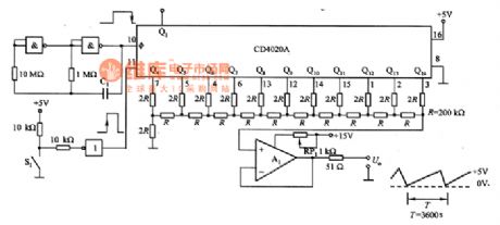
The long cycle sawtooth wave generator circuit composed of the CD4020A is as shown in the figure. The CD4O2OA is designed as the 14-level binary counter, the output port of it is connected with the R-2R trapezoidal network, it can output the analog voltage according to the clock pulse in the D/A conversion, at this time, it changes into the D/A converter. The R-2R trapezoidal network has the small resistance value, and the error is large, so we use the 200kΩ resistor. This circuit uses the 11-bit of the Q1~Q14 of CD4020A, the minimum resolution is 5/2048(V), the Q1~Q3 can be used as the frequency divider only. The oscillation period of this circuit is set to 1h, you can change the oscillation period by setting the oscillation frequency.
(View)
View full Circuit Diagram | Comments | Reading(1751)
sixteen pulses generator circuit composed of the SN74123
Published:2011/8/28 20:18:00 Author:TaoXi | Keyword: sixteen pulse, generator
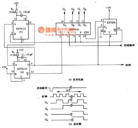
The sixteen pulses generator circuit which is composed of the SN74123 is as shown in the figure. When you input the negative pulse starting signal, it will produce the 1.2μS sixteen pulses, and the negative edge of the pulse controls the end of the counting, so we get the output of the counter. If you decode the output of the counter and use the pulse as the timing, so you can control the order of synchronous circuit.
The figure 6-40(a) shows the practical circuit, it is composed of the multivibrator which is composed of the SN74123 and SN7476, the counter which is composed of the SN74161, the start/stop control part of the counter.
(View)
View full Circuit Diagram | Comments | Reading(2623)
PLL pulse generator circuit composed of the TC5082
Published:2011/8/28 20:32:00 Author:TaoXi | Keyword: PLL, pulse, generator circuit
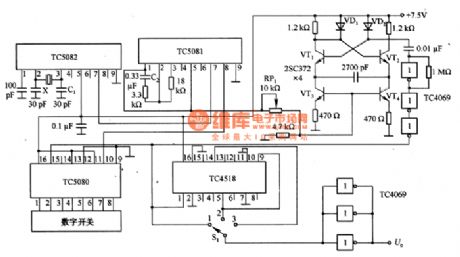
The PLL pulse generator circuit which is composed of the TC5082 is as shown in the figure. In this circuit, the x is the l0.24MHZ crystal oscillator, you can get the 10kHz reference frequency through the TC5082, and you can use the C1 to adjust the reference frequency. VT1~VT4 are the voltage-controlled oscillator, it is designed as the emitter coupling multivibrator, you can change the value of RP1 to make it oscillate in the range of 100~990kHZ. The output of the voltage-controlled oscillator is amplified by the TC4069, the amplified signal adds to the clock input port of the TC5080 (pin-15). The frequency divider circuit uses the TC4518, the output port has the buffer which is composed of the three inverter of the TC4069, the purpose of the parallel connection is to improve the driving capability.
(View)
View full Circuit Diagram | Comments | Reading(2609)
Sawtooth wave generator circuit composed of the NE555
Published:2011/8/28 20:49:00 Author:TaoXi | Keyword: Sawtooth wave, generator circuit
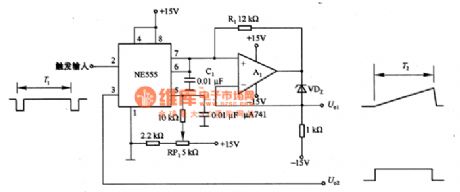
The sawtooth wave generator circuit which is composed of the NE555 is as shown in the figure. It uses the NE555 to charge the timing capacitance to produce the sawtooth wave. In the figure 6-38(a), the follower which is composed of A1 uses the bootstrap mode, the charging current of C1 is decided by the voltage-regulator diode VDZ and the resistor R1. Because the bootstrap mode is different with the mueller integral circuit, the power supply which supplies the power to the C1 is in the floating State, so it will not influences by the changing of the power supply voltage.
You can change the value of R1 or C1 by changing the cycle of the sawtooth wave, also you can use the voltage-regulator diodes with different values to change the cycle of the sawtooth wave.
(View)
View full Circuit Diagram | Comments | Reading(2342)
Function generator circuit composed of the AD7520
Published:2011/8/28 22:40:00 Author:TaoXi | Keyword: Function generator
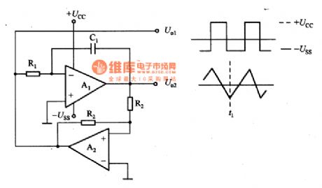
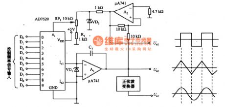
The function generator circuit which is composed of the AD7520 is as shown in the figure. The function generator basic circuit which is as shown in figure 6-37(a) is composed of the integrator A1 and the comparator A2. In the moment of T1, if the output of A2 reaches the negative saturation voltage-Uss, the output of A1 will be U. When 1+U2=0, the output of A2 will reverse, the -Uss will change into the +Ucc, the output of A1 will decrease to U. When 1+U2=0, it will reverse again. The circuit will produce the oscillation, the time constant is decided by the T=R1C1. So we can control the frequency oscillation by changing the value of R1.
(View)
View full Circuit Diagram | Comments | Reading(2390)
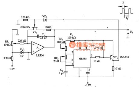
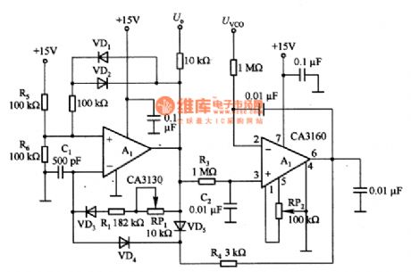
Sawtooth wave generating circuit composed of the μA741
Published:2011/8/28 22:51:00 Author:TaoXi | Keyword: Sawtooth wave, generating circuit
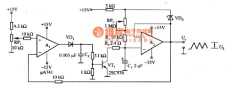
The sawtooth wave generating circuit which is composed of the μA741 is as shown in the figure. It is composed of the bootstrap circuit and the comparator. If Us is 10V, the C1 will not be charged. The output of A1 will be clamped to negative value, the VT1 cuts off. Because the output of A2 is zero, so the stable voltage power supply Uz of VD2 will add to RP2 and R1, there is the constant current. The constant current charges C1, because the A2 is the voltage follower, the output voltage of A2 is the same as the voltage of C1. The voltage of RP2 and R1 is decided by the VDZ, so the constant current continues to charge the C1. The output voltage of A2 increases linearly with the time.
(View)
View full Circuit Diagram | Comments | Reading(805)
Sawtooth wave generating circuit composed of the LM301
Published:2011/8/28 23:03:00 Author:TaoXi | Keyword: Sawtooth wave, generating circuit
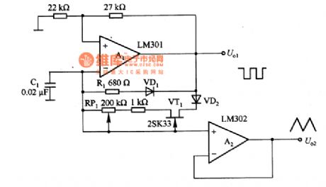
The sawtooth wave generating circuit which is composed of the LM301 is as shown in the figure. The timing resistor of the multivibrator is devided by VD1 and VD2, and it uses the charging and discharging voltage of C1 to produce the sawtooth wave. A1 is the level comparator, when the output of it is positive, the VD1 cuts off, the VD2 conducts, the current which is added to C1 is produced by the constant current source which is composed of VT1, so the voltage straights up. When the output of A1 is negative, the VD2 cuts off, the VD1 conducts, the timing resistor changes into R1, the fall time is less than the rise time. The voltage of C1 is the sawtooth wave voltage, it is output by the buffer amplifier A2.
(View)
View full Circuit Diagram | Comments | Reading(1845)
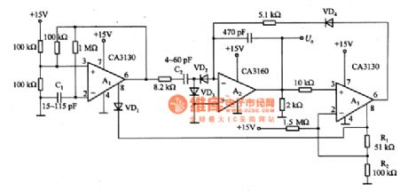
Broadband function generator circuit
Published:2011/8/29 1:25:00 Author:TaoXi | Keyword: Broadband, function, generator
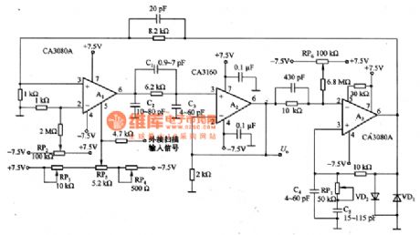
The broadband function generator circuit is as shown in the figure, the frequency range is 1HZ~1MHZ. In the circuit, the A2 is operating in the voltage follower state and it has the buffer function. A3 is the high-speed comparator that can be used to detect the positive and negative amplitude of the triangle wave output waveform, it switches the control voltage which is added on the constant current source. A1 is the program-controlled constant current source, the output DC adds to the RC network, and this output DC is integrated to be the triangle waveform.
The C1~C3 can be used to adjust the output waveform of the triangle wave, you can get the triangle waveform with good linearity by adjusting the three capacitors in the range of 5OOkHZ~1MHz.
(View)
View full Circuit Diagram | Comments | Reading(2170)
Triangular wave generation circuit with the adjustable amplitude
Published:2011/8/29 2:09:00 Author:TaoXi | Keyword: Triangular wave, generation circuit, adjustable amplitude
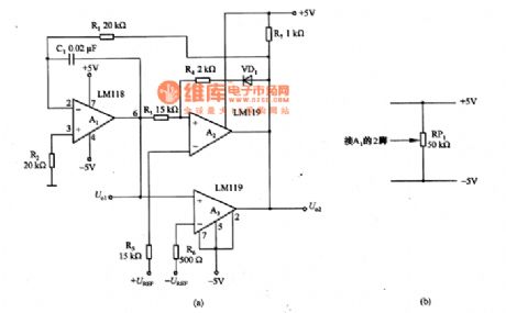
The triangular wave generation circuit with the amplitude that can be adjusted accurately is as shown in the figure, the accuracy of the amplitude is +/-0.01V, if you add the +UREF and -UREF DC voltage, the amplitude of the triangular wave can be the positive and negative peak values.
The circuit is composed of the integrator which is composed of A1, the positive and negative peak values judgment comparators A2 and A3. The U1 outputs the triangular wave, the U2 outputs the square wave. You can change the frequency of the output signal by changing the value of R1. The symmetrical characteristic of the waveform can be adjusted. At this time, you can connect the potentiometer RP1 with the positive and negative power supplies (figure 6-29(b)).
(View)
View full Circuit Diagram | Comments | Reading(875)
Ladder wave generation circuit composed of the LM3900
Published:2011/8/28 19:51:00 Author:TaoXi | Keyword: Ladder wave, generation circuit

The ladder wave generation circuit composed of the LM3900 is as shown in the figure. The A1 forms the oscillation part of the ladder wave input pulse through the resistor R1. A2 has the integral and holding functions and it can get the ladder wave from the output. A3 and A4 have the functions of the comparator circuit and the monostable multivibrator.
R2 can be used in the sampling of the ladder wave's output, it compares with the power supply voltage +Ucc through the resistor R3. When the output voltage of A2 is more than 80% of +Ucc, the A3 and A4 produce the 100μs reset pulse, and it makes the output of the integrator A2 to 0V.
(View)
View full Circuit Diagram | Comments | Reading(1544)
Ladder wave generation circuit
Published:2011/8/29 1:37:00 Author:TaoXi | Keyword: Ladder wave, generation circuit
The ladder wave generation circuit is as shown in the figure. In this circuit, the A1 is the multivibrator which produces the square wave, and it is controlled by the 8-pin of the selective passing port. A2 is the integrator, the output of it is the ladder wave, the operating state of it is controlled by the delay switch. A3 is the delay amplifier, it makes the output of selective passing port's 8-pin divide by R1 and R2, and it adds the positive feedback to pin-2 to make it have the delay characteristic. The C1 can be used to adjust the frequency of the multivibrator, the C2 can be used to adjust the stepping height, the VD1 can be used to prevent the reversal of the multivibrator, VD2 and VD3 are the charging commutation circuit.
(View)
View full Circuit Diagram | Comments | Reading(826)
Triangle wave generator uses the luminous flux to change the frequency
Published:2011/8/28 20:03:00 Author:TaoXi | Keyword: Triangle wave, generator, luminous flux, frequency

Triangle wave generator which uses the luminous flux to change the frequency is as shown in the figure. A part of the timing resistor of the function generator uses the photoconductive resistance RG to change the frequency through the luminous flux. The complementary re-flip flop which is composed of VT1 and VT2 inspires the RG. The resistance attenuator is composed of the R1, R2 and R3 that can be used to improve the input impedance of μPC55A, and it makes the frequency extend upward. The RP2 can be used to adjust the symmetrical characteristic of the output amplitude.
(View)
View full Circuit Diagram | Comments | Reading(884)
Voltage-controlled oscillator circuit
Published:2011/8/29 1:52:00 Author:TaoXi | Keyword: Voltage-controlled, oscillator circuit
The voltage-controlled oscillator circuit is as shown in the figure. The input voltage range of the oscillator is 0-10V, the change sensitivity is 1kHz/V, the tracking error is 0.02%, the temperature coefficient is 0.01%. The multivibrator is composed of A1 that can produce the constant amplitude and constant pulse width rectangular wave, the output amplitude is the positive and negative power supply voltage. The rectangular wave which is output by A1 is processed by the integration circuits R3 and C2 to be the average voltage, this average voltage adds to the in-phase inout port of the comparator A2. The A2 is in the state of the input voltage is the same as the rectangular wave average voltage, and it adds the output to the reverse-phase input port of A1 through the R4 and VD4 to change the deadline of the multivibrator.
(View)
View full Circuit Diagram | Comments | Reading(1094)
Differential filter circuit diagram
Published:2011/8/24 22:01:00 Author:Ecco | Keyword: Differential filter

View full Circuit Diagram | Comments | Reading(730)
n circuit diagram of EMI filter
Published:2011/8/24 22:10:00 Author:Ecco | Keyword: n circuit , EMI filter
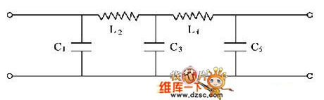
In the Figure, C1 = 6.4μF, L2 = 3.5mH, C3 = 8.4μF, L4 = 3.5mH, C5 = 6.4μF. If the input and output load resistance is 50Ω, the circuit in Figure 1 is made Laplace transformation, then you can find the frequency response of LC filter circuit in the low end insertion loss.
(View)
View full Circuit Diagram | Comments | Reading(1106)
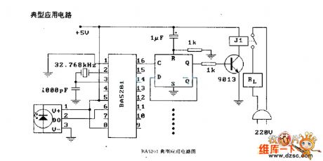
BA5201 (household appliance) infrared remote control decoding circuit diagram
Published:2011/8/25 1:11:00 Author:Ecco | Keyword: household appliance, infrared remote control , decoding
View full Circuit Diagram | Comments | Reading(679)
Transformer oscillator(single tube) circuit diagram
Published:2011/8/25 1:40:00 Author:Ecco | Keyword: Transformer oscillator, single tube

View full Circuit Diagram | Comments | Reading(841)
Square wave and sawtooth wave generation circuit composed of the MAM4162
Published:2011/8/23 22:29:00 Author: | Keyword: Square wave, sawtooth wave, generation circuit
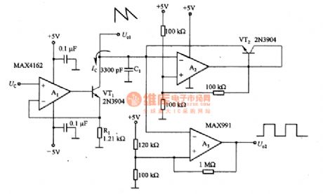
The square wave and sawtooth wave generation circuit composed of the MAM4162 is as shown in the figure. The linearity of this kind of circuit is higher than 1%, the dynamic range can be 80dB. In the circuit, the voltage controlled current source is composed of the A1, VT1 and R1. The capacitance C1 discharges through the current Ic until the voltage of it is reduced to 1.66V, the comparator A2 outputs the +5V voltage. The current of VT2 charges the capacitance C1 until the voltage of it is 3.33V, the output of A2 closes to the ground level. When the control voltage Uc=1.66V, the output frequency is maximum. You can change the value of R1 and C1 to make it output the expected value, the upper limit frequency is limited by the rise time of A2.
(View)
View full Circuit Diagram | Comments | Reading(2283)
Random code generation circuit composed of the LTC1340
Published:2011/8/23 22:29:00 Author: | Keyword: Random code, generation circuit
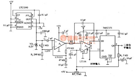
The random code generation circuit which is composed of the LTC1340 is as shown in the figure. This circuit uses the 6.2V voltage-regulator diode VD1 to produce the random noise with the best features. We can find that this circuit outputs the best noise at the bending place of the zener diode characteristic curve, it is the starting place of the 6.2V stable voltage. The operating voltage of the circuit is +5V. In order to let the VD1 get the 6.2V stable voltage, we use the LTC1340 as the boost converter to improve the +5V to +8V (the output voltage of the pin-7 is 9.2V). The resistors R1 and R2 supply the 1.25V bias voltage to A1 to make it match with the input common-mode signal range of the comparator A2.
(View)
View full Circuit Diagram | Comments | Reading(633)
Sawtooth wave generating circuit composed of the LM747
Published:2011/8/14 19:45:00 Author:TaoXi | Keyword: Sawtooth wave, generating
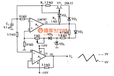
The sawtooth wave generating circuit which is composed of the LM747 is as shown in the figure. It uses the self-excited multivibrator to produce the sawtooth wave. In order to make the capacitance C1's chargig voltage line increase linearly, we use the constant current source which is composed of the VT1 and R1. And in order to reduce return time of the sawtooth wave, the VD1 and R2 supply the discharging circuit which has very small discharge time constant. The voltage-regulator diode VD5 clamps the output of A1 to stabilize the output amplitude of it. When the C1 is discharging, if you supply the reverse bias to the VD5, the VD4 will cut off, the in-phase input port of A1 is 0V, the minimum level of the sawtooth wave goes back to 0V.
(View)
View full Circuit Diagram | Comments | Reading(1832)
| Pages:56/195 At 204142434445464748495051525354555657585960Under 20 |
Circuit Categories
power supply circuit
Amplifier Circuit
Basic Circuit
LED and Light Circuit
Sensor Circuit
Signal Processing
Electrical Equipment Circuit
Control Circuit
Remote Control Circuit
A/D-D/A Converter Circuit
Audio Circuit
Measuring and Test Circuit
Communication Circuit
Computer-Related Circuit
555 Circuit
Automotive Circuit
Repairing Circuit