Signal Processing
Sawtooth wave generator circuit composed of the NE555
Published:2011/8/28 20:49:00 Author:TaoXi | Keyword: Sawtooth wave, generator circuit | From:SeekIC


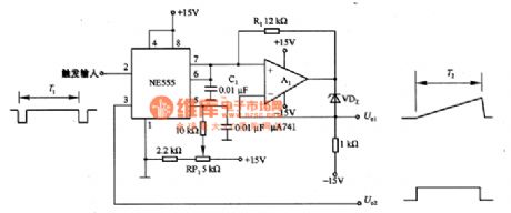
The sawtooth wave generator circuit which is composed of the NE555 is as shown in the figure. It uses the NE555 to charge the timing capacitance to produce the sawtooth wave. In the figure 6-38(a), the follower which is composed of A1 uses the bootstrap mode, the charging current of C1 is decided by the voltage-regulator diode VDZ and the resistor R1. Because the bootstrap mode is different with the mueller integral circuit, the power supply which supplies the power to the C1 is in the floating State, so it will not influences by the changing of the power supply voltage.
You can change the value of R1 or C1 by changing the cycle of the sawtooth wave, also you can use the voltage-regulator diodes with different values to change the cycle of the sawtooth wave.
Reprinted Url Of This Article:
http://www.seekic.com/circuit_diagram/Signal_Processing/Sawtooth_wave_generator_circuit_composed_of_the_NE555.html
Print this Page | Comments | Reading(3)

Article Categories
power supply circuit
Amplifier Circuit
Basic Circuit
LED and Light Circuit
Sensor Circuit
Signal Processing
Electrical Equipment Circuit
Control Circuit
Remote Control Circuit
A/D-D/A Converter Circuit
Audio Circuit
Measuring and Test Circuit
Communication Circuit
Computer-Related Circuit
555 Circuit
Automotive Circuit
Repairing Circuit
Code: