
Signal Processing
Index 61
ELECTRIC_TUNING_FOR_50_MC_F_M_RANGE
Published:2009/7/14 23:06:00 Author:Jessie
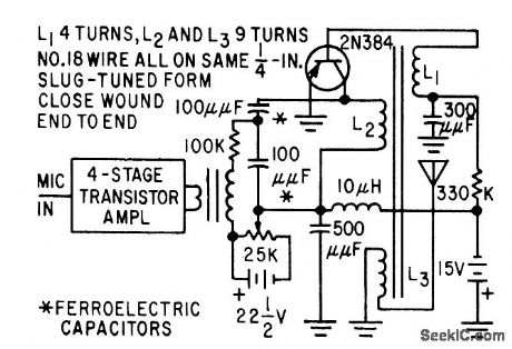
Used two voltage-tunable ferroelectric capacitors. Can be built in pocket-size plastic case when powered with hearing-aid batteries.-T. W. Butler, Jr., Ferroelectrics Tune Electronics, Circuits, Electronics, 32:3, p 52-55. (View)
View full Circuit Diagram | Comments | Reading(685)
LOW_COST_IC_TUNER
Published:2009/7/14 23:04:00 Author:Jessie
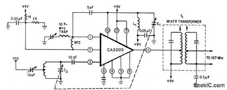
Front end uses single RCA three-transistor two-diode chip with conventional tuning circuit. Ganged capacitors C1.C2 are 5-22 pf. Power gain is 15 db and sensitivity is 10 microvolts for 30 db of quieting. Performance is just adequate for low-cot commercial f-m tuner.-R. L. Sanquini, Integrated Circuits Make A Low-Cost F-M Receiver, Electronics, 39:16, p 133-138. (View)
View full Circuit Diagram | Comments | Reading(1353)
CONTROL_FOR_VOLTAGE_TUNED_OSCILLATOR
Published:2009/7/14 20:39:00 Author:May

Input d-c control voltage required by SiC varistors of voltage-tuned oscillator is boosted by d-c amplifier stages that produce two control voltages (at A and B) for SiC varistors of phase-shift oscillator circuit, changing their a-c resistance and thereby oscillator frequency.-M. Uno, Varistor Network Controls Voltage-Tuned Oscillator, Electronics, 34:30, p 44-47. (View)
View full Circuit Diagram | Comments | Reading(902)
STEREO_MULTIPLEX_TUNER
Published:2009/7/14 22:57:00 Author:Jessie

Consists of demodulator D1-D2, 19-38 kc doubler Q3 19-kc amplifier Q2, composite amplifier Q2, and stereo station indicator Q4 with lamp. Diodes are 1N60. Uses lime-share method that eliminates need for 15.kc low-pass fiber and 23-53 kc bandpass filter.-R. Brubaker, A Low Cost All Solid-Slate FM Stereo Multiplex System, Motorola Application Note AN-207, Mar. 1966. (View)
View full Circuit Diagram | Comments | Reading(828)
VARACTOR_MODULATES_24_MC_F_M_OSCILLATOR
Published:2009/7/14 22:53:00 Author:Jessie

Modulating signal is applied to vat deviation of 60 kc.-N. Downs and B. varactor diode in frequency-determining circuit of telemetering oscillator. Linearity is 2% for deviation of 60 kc.-N. Downs and B. van Sutphin, Solid-State Transmitter Ready for UHF Telemetry, Electronics, 37:17, p 76-80. (View)
View full Circuit Diagram | Comments | Reading(730)
SELF_REACTANCE_MODULATION
Published:2009/7/14 22:51:00 Author:Jessie
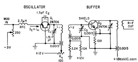
Modulation current injected at emitter changes collector-base voltage, thus varying output capacitance, tank resonant frequency, and oscillator frequency +or 230-Mc pam/f-m telemetery beacon.-T. M. Conrad, Self-Reactance Modulation in Telemetry Oscillators, Electronics, 35:9, p 35-37. (View)
View full Circuit Diagram | Comments | Reading(1233)
200_MC_VOLTAGE_CONTROLLED_OSCILLATOR
Published:2009/7/14 22:50:00 Author:Jessie

Uses two tunnel-diodes in astable mvbr to give symmetrical square wave output. Used to produce wide frequency swing with respect to center frequency, linearly, when small control voltage is applied.-F. H. Lefrak, Tunnel-Diode Oscillator Expands F.M System's Tunnel-Diode Oscillator Expands F-M System's Channel Capacity, Electronics ,39:1, P 105-109. (View)
View full Circuit Diagram | Comments | Reading(785)
VOLTAGE_TO_FREQUENCY_CONVERTER
Published:2009/7/14 22:50:00 Author:Jessie
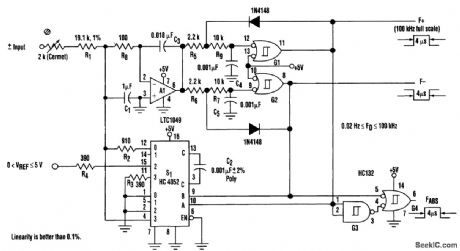
The voltage-to-frequency converter draws <10 mA from one +5-V supply while producing three 0- to 100-kHz pulse outputs.One output is proportional to positive input voltages and inactive for negative inputs, another responds when the input is negative, and a third outputs a frequency that is proportional to the input's absolute value. The converter's unadjusted zero offset is less than 1 ppm of full scale and its linearity is better than 0.1 percent. (View)
View full Circuit Diagram | Comments | Reading(0)
VOLTAGE_CONTROLLED_CRYSTAL
Published:2009/7/14 20:33:00 Author:May

Voltage-variable capacitance tuning diode in series with crystal feedback path of Motorola MC10116 IC gives frequency deviation of about ±50 PPM for 1-MHz crystal when using tuning voltage range of 0-25 VDC. Deviation is greater at higher crystal frequencies.-B. Blood, IC Crystal Con-trolled Oscillators, Motorola, Phoenix, AZ, 1977, AN-417B, p 6.
(View)
View full Circuit Diagram | Comments | Reading(1426)
PRECISION_SIGNAL_RECTIFIER
Published:2009/7/15 4:00:00 Author:Jessie

High input impedance at one of differential inputs of precision rectifier is achieved with opamp A1 whose output is switched between inputs of in-strumentation amplifier A2 by diodes. This switching reverses polarity of gain provided by A2, when signal polarity changes, so output signal is always positive.-J. Graeme, Measure Differential AC Signals Easily with Precision Rectifiers, EDN Magazine, Jan. 20, 1975, p 45-48. (View)
View full Circuit Diagram | Comments | Reading(717)
BUSY_SIGNAL_GEN_ERATOR
Published:2009/7/14 8:36:00 Author:May
Conventional Bell System busy signal is provided by turning twin-T oscillator at left on and off with low-frequency asymmetrical square wave generated by transistor pair at right. Q1 acts as switch for turning oscillator on and off. Developed for use at repeater in home when autopatch connects to family telephone, to inhibit use of autopatch by mobile station when phone is in use. Article also covers connections to phone line and to repeater.-T. Yocom, An Autopatch Busy Signal, 73 Magazine, Holiday issue 1976, p 148 and 150. (View)
View full Circuit Diagram | Comments | Reading(834)
500_MC_TO_4000_MC_1_STEP_MULTIPLIER
Published:2009/7/15 2:56:00 Author:Jessie
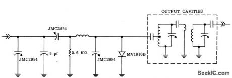
Combines both lumped and coaxial cavity techniques with varctctor to serve as octupler. Coupling from varctctor to first cavity must be exceedingly tight.-G. Schaffner, Varactor Multipliers Provide High Output-Power Above 6 GHz, Motorola Application Note AN.213, Dec. 1965. (View)
View full Circuit Diagram | Comments | Reading(685)
TRIPLER_WITH_OVERLAY_TRANSISTOR_GIVES_102_GC
Published:2009/7/15 2:55:00 Author:Jessie
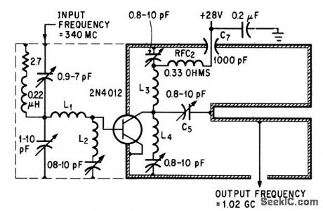
Single overlay transistor eliminates conventional transistor amplifier and chain of varactor frequency multipliers. Output power is 3.5 w.-H. C. Lee and G. J. Gilbert, Overlay Transistors Move into Microwave Region, Electronics, 39:6, p 93-95. (View)
View full Circuit Diagram | Comments | Reading(764)
200_MC_TO_600_MC_HARMONIC_TRIPLER
Published:2009/7/15 2:55:00 Author:Jessie
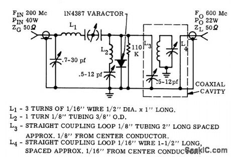
Uses single varactor to give 20 w output from 40 w input.-G. Schaffner and J. Cochran, Varactor Diodes and Circuits for High Power Output and Linear Response, Motorola Application Note AN-191, Aug. 1965. (View)
View full Circuit Diagram | Comments | Reading(681)
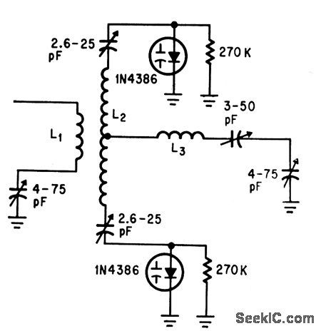
50_MC_TO_100_MC_PUSH_PUSH_DOUBLER
Published:2009/7/15 2:53:00 Author:Jessie
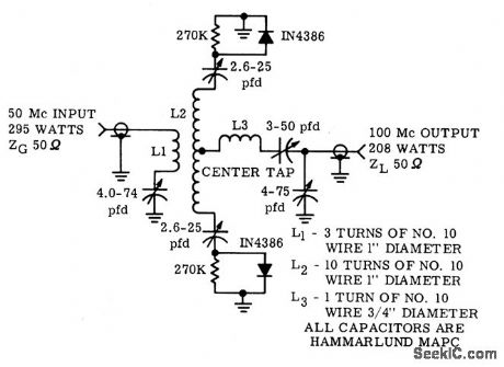
Two 1N4386 varactors are connected in phrase opposition to input signal and parallel to common load at even harmonic signal, to give action comparable to push-push circuit. Power-handling capacity is twice that of single varactor, with added benefit of odd-harmonic suppression.-G. Schaffner and J. Cochran, Varactor Diodes and Circuits for High Power Output and Linear Response, Motorola Application Note AN-191, Aug. 1965. (View)
View full Circuit Diagram | Comments | Reading(761)
50_MC_TO_200_MC_VARACTOR_QUADRUPLER
Published:2009/7/15 2:51:00 Author:Jessie
Uses 1N4386 varactor capable of handling 50 w input power up to 300 Mc. Gives efficiencies up to 70%.-G. Schaffner, High Power Varactor Diodes, Motorola Application Note AN-147, Apr. 1964. (View)
View full Circuit Diagram | Comments | Reading(717)
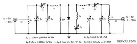
50_100_MC_PUSH_PUSH_DOUBLER
Published:2009/7/15 2:50:00 Author:Jessie
Charge-storage 1N4386 varactors in push-push provide 180 w. output with 70% effciency.-G.Schaffner, Charge Storage Varactors Boost Harmonic Power, Electronics, 3710, p 42-47. (View)
View full Circuit Diagram | Comments | Reading(754)
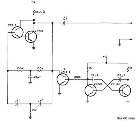
100_KC_TO_5_MC
Published:2009/7/15 2:49:00 Author:Jessie
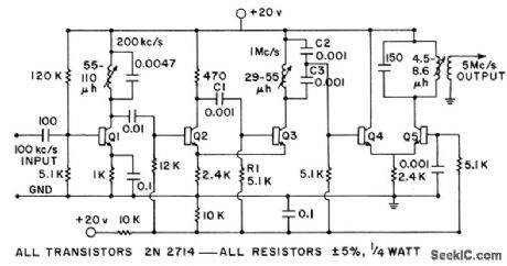
Simple transistor circuit converts 100-kc standard frequency of frequency counter to 5 Mc for use with 500-Mc frequency converter which requires 5.Mc reference frequency. Q1 is doubler. Q2 and Q3 form unique quintupler evolved from Schmitt trigger, in which square-wave symmetry is preserved by maintaining triggering point at zero crossings of input signal. Q4-05 is similar quintupler, but without cross-coupling feedback.-H. T. McAleer, Unique Frequency Multiplier, Frequency, May-June 1964, p 36-37. (View)
View full Circuit Diagram | Comments | Reading(797)
CASCADED__UHF_DOUBLERS
Published:2009/7/15 2:47:00 Author:Jessie
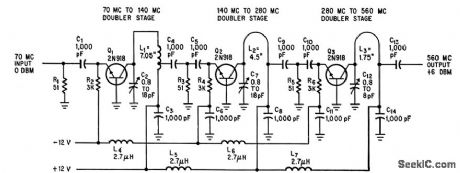
Common-base amplifier with tank circuit tuned to twice the input frequency is cascaded to give frequency multiplication in 40 to 1,000 Mc range, with power output per stage ranging from 50% of stage d-c supply at low frequencies to 25% at high frequencies.-A. E. Munich, Basic UHF Circuit Forms Amplifiers and Multipliers, Electronics, 37:20, p 59-60. (View)
View full Circuit Diagram | Comments | Reading(790)
TWO_DOUBIERS_AND_QUADRUPLER_GIVE_960_MC
Published:2009/7/15 2:46:00 Author:Jessie
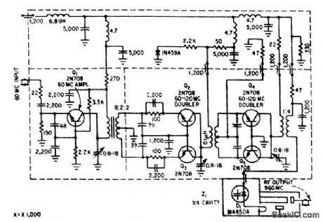
First two doublers are push-push class C with unity gain. Varactor D1 in final multiplier, feeding 960.Mc quarter-wave series-resonance coaxial cavity, acts as quadrupler.-W. E. Dahl, Communicating with Future Deep-Space Probes, Electronics, 36:22, p 28-32, (View)
View full Circuit Diagram | Comments | Reading(673)
| Pages:61/195 At 206162636465666768697071727374757677787980Under 20 |
Circuit Categories
power supply circuit
Amplifier Circuit
Basic Circuit
LED and Light Circuit
Sensor Circuit
Signal Processing
Electrical Equipment Circuit
Control Circuit
Remote Control Circuit
A/D-D/A Converter Circuit
Audio Circuit
Measuring and Test Circuit
Communication Circuit
Computer-Related Circuit
555 Circuit
Automotive Circuit
Repairing Circuit