
Signal Processing
Index 60
MEASURING_1_CPS_F_M_DEVIATION
Published:2009/7/14 22:10:00 Author:Jessie
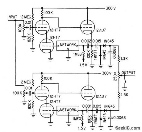
Foster-Seely discriminator uses RC elements in feed-back loops of amplifiers to simulate conventional LC tuned circuits. Upper cascode amplifier, cathode follower, and feedback loop resonate slightly above center frequency, while lower half of circuit resonates below center frequency. Circuit works well up to 500 kc.-H. D Crawford, F-M Discriminator Without Tuned Circuits, Electronics,36:48, p 36. (View)
View full Circuit Diagram | Comments | Reading(560)
FLOWMETER_FREQUENCY_CONVERTER
Published:2009/7/14 22:01:00 Author:Jessie
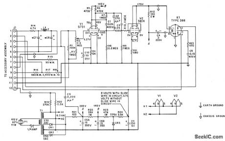
Provides output signal that is directly provides output signal that is directly proportional to frequency of input from ,turbine flow-sensing element, for driving associated electronic potentiometer. V1 and V2 form three-stage limiting amplifier. Capacitor tachometer circuit uses chopper K1 to discharge C5 repetitively through adjustable-range resistor. Adjustable precision resistor in series with slide-wire of potentiometer provides accurate manual compensation for changes in specific gravity of measured medium. Circuit is Potter model 11-B frequency converter.-G. C. Carrol, Industrial Instrument Servicing Handbook, McGraw-Hill, N.Y., 1960, p 3-3. (View)
View full Circuit Diagram | Comments | Reading(831)
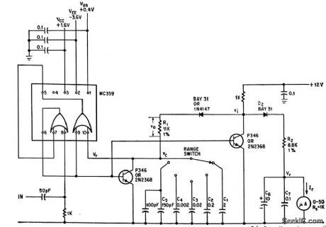
I_F_BESS_DIGITAL_FREQUENCY_METER
Published:2009/7/14 22:00:00 Author:Jessie
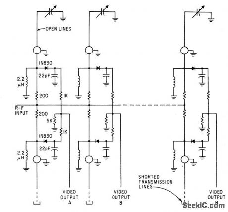
Binary Electromagnetic Signal Signature (bess) concept permits measuring frequency of single r-f pulse in range of 55 to 65 Mc. Eight pairs of Iransmission lines divide this band into eight equal segments of 1.25 Mc. Same con cope con be applied to other ranges up to 4,000 Mc.-R. F. Morrison, Jr., and M. N. Sarachan, Binary Frequency Sensing Measuresa SinglePulse, Electronics, 36:14, p 42-46. (View)
View full Circuit Diagram | Comments | Reading(683)
CABLE_PROPAGATION_DELAY_TIME
Published:2009/7/14 22:23:00 Author:Jessie
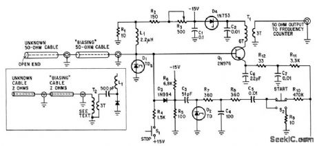
Pulse generated by tunnel diode travels to end of 50-ohm cable, is reflected back, and retriggers tunnel diode to repeal process. Resulting repetition rate of pulses, measured with circuit feeding frequency meter, gives delay time with high accuracy. Transformer (lower left) permits measuring cables of other impedances.-P. J. Kindlmann, Tunnel-Diode Pulser Measures Cable Delay,Electronics,39:4,p 87-88. (View)
View full Circuit Diagram | Comments | Reading(1170)
PULSE_RATE_METER
Published:2009/7/14 22:12:00 Author:Jessie


Current pulse width is controlled by feedback voltage proportional to charge on output capacitor, to insure that each input pulse feeds exactly the same charge to the output circuit.-R. J. Smith-Saville and S. Ness, Charge Feedback Increases Pulse-Rate Meter Accuracy, Electronics, 39:3, p 85-86. (View)
View full Circuit Diagram | Comments | Reading(1050)
TWO_PHASE_OSCILLATOR
Published:2009/7/14 22:11:00 Author:Jessie

Unknown signal to be analyzed is multiplied independently by each of two output reference signals, A and B. Oscillator uses two 90° phase-shift networks and 180° of phase shift in amplifier. Gain of 0.98 in cathode follower makes circuit accurate over 10:1 frequency range.-T. B. Fryer, Frequency Analyzer Uses Two Reference Signals, Electronics, 32:18, p 56-57. (View)
View full Circuit Diagram | Comments | Reading(755)
FREQUENCY_MONITOR_CONTROLS_DEPOSITION_OF_THIN_FILMS
Published:2009/7/14 22:24:00 Author:Jessie
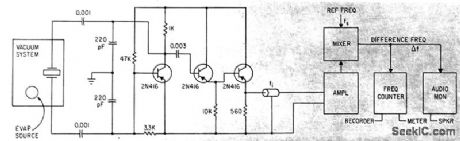
Film is deposited on quartz crystal mounted alongside substrate in vacuum, causing crystal frequency to change. Amplified output of Colpitts crystal oscillator is fed through coax to mixer that also receives reference frequency, and beat-frequency difference (related to film thickness) is indicated on counter.-S. J. Lins and P.E. Oberg, Avtomatic Deposition Control, Electronics, 36:13,P 33-35. (View)
View full Circuit Diagram | Comments | Reading(678)
WEAK_SIGNAL_CAPTURE
Published:2009/7/14 22:32:00 Author:Jessie
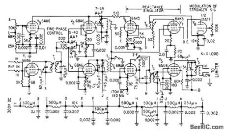
High-Q trap in reactance-tube circuit attenuates stronger of two signals, to permit capture of weaker of two cochannel f-m signals, as often required in police, military, and telemetering systems, Trap introduces depression in frequency re sponse of third i-f stage, centered on frequency of stronger signal.-E. J, Baghdady and G. J. Rubissow, Dynamic Trap Captures Weak F-M Signals, Electronics, 32:2, p 64-66. (View)
View full Circuit Diagram | Comments | Reading(926)
VOLTAGE_CONTROLLED_DELAY_GENERATOR
Published:2009/7/14 21:36:00 Author:May
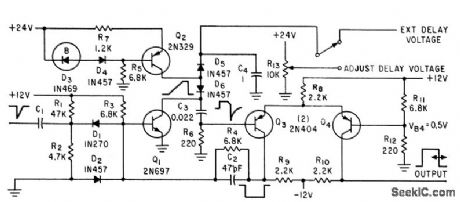
Accuracy is 0.7%,with high stability. Used in radar range tracker, which requires accurate voltage analog of time between out going pulse and incoming echo.-C. K. Friend and S. Udalov, Stabilized Delay Circuit Provides High Accuracy, Electronics, 34:15, p 78-80. (View)
View full Circuit Diagram | Comments | Reading(726)
CASCADED_UJT_RELAXATION_OSCILLATOR_DIVIDER
Published:2009/7/14 21:36:00 Author:May

Class C Hartley master oscillator serves for synchronizing three basic relaxation oscillators that would otherwise be free-running. Dividers remain locked over temperature range of 0 to 70℃.- Transistor Manual, Seventh Edition, General Electric Co., 1964, p 342. (View)
View full Circuit Diagram | Comments | Reading(1575)
TWO_CHIP_TUNER
Published:2009/7/14 22:32:00 Author:Jessie
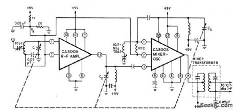
Use of additional RCA integrated-circuit chip as r-f amplifier improves gain and selectivity, while boosting sensitivity to 3 microvolts.-R. L. Sanquini, Integrated Circuits Make A Low-Cost F-M Receiver, Electronics, 39:16, p 133-138. (View)
View full Circuit Diagram | Comments | Reading(1035)
100_MC_VRAICAP_OSCILLATOR
Published:2009/7/14 22:40:00 Author:Jessie

Modulator consists of two variable-capacitance diodes in series to r-f and in parallel to audio modulating signals and d-c bias. Frequency deviation is 28 Mc peak-to-peak with modulating signals less thon 28 v and negligible modulating power.-C. Arsem, Wideband F-M with Capacitance Diodes, Electronics, 32:49, p 112-113. (View)
View full Circuit Diagram | Comments | Reading(708)
1_MC_F_M_OSCILLATOR
Published:2009/7/14 22:38:00 Author:Jessie

Combines Q multiplier with Miller effect to produce simple and stable f-m oscillator and modulator.-P. W. Wood, Transistorized F-M Oscillator, Electronics, 32:5, p 64. (View)
View full Circuit Diagram | Comments | Reading(901)
PLL_ULTRASONIC_GENERATOR
Published:2009/7/14 21:21:00 Author:May
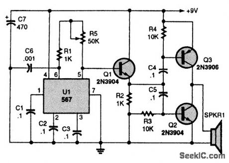
This ultrasonic generator is built around a 567 PLL. By adding a telegraph key, as described in the text, it can be turned into an ultrasonic transmitter. (View)
View full Circuit Diagram | Comments | Reading(2316)
CMOS_ULTRASONIC_GENERATOR
Published:2009/7/14 21:18:00 Author:May
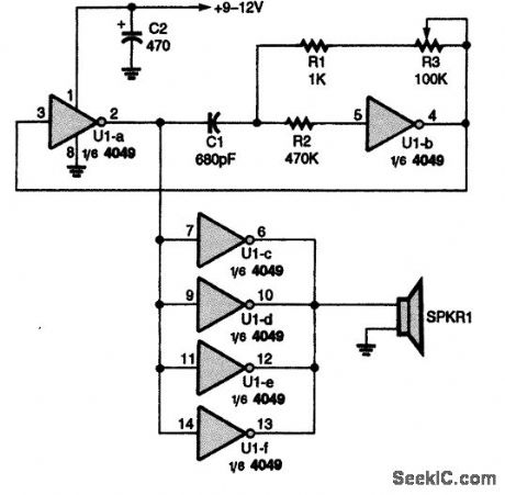
This ultrasonic generator uses a single CD4049IC. The frequency range is about 15 to 50 kHz. (View)
View full Circuit Diagram | Comments | Reading(2317)
STRAIN_GAGE_OSCILLATOR
Published:2009/7/14 23:26:00 Author:Jessie


Produces f-m signal output that is directly proportional to applied force, such as stress or pressure resistive-type gage. Operating and band, edge frequencies of oscillator are determined by values of R, L, and C.-W. H. Foster, Strain Gage Oscillator for Flight Testing, Electronics, 31:5, p 40-42. (View)
View full Circuit Diagram | Comments | Reading(733)
QUADRATURE_OSCILLATOR_USES_MULTI
Published:2009/7/14 20:48:00 Author:May

PLIERS-4214 differential multipliers eliminate need for opamps in quadrature oscillator in which frequency is controlled by external DC voltage. R3, R4, R5, and D1 form diode limiter, while R1,R2,and C1,provide positive feedback to sustain oscillation,R1 should be about equal to R, R2about 20R, and C1 about 10C. R2 can be readjusted for best compromise between distortion and speed of amplitude buildup.-Y. J. Wong, Design a Low Cost, Low-Distortion, Precision Sine-Wave Oscillator, EDN Magazine, Sept. 20, 1978, p 107-113. (View)
View full Circuit Diagram | Comments | Reading(973)
400_MC_VARICAP_OSCILLATOR
Published:2009/7/14 23:24:00 Author:Jessie

Wideband frequency modulation of 400-Mc distributed-parameter Colpitts oscillator is obtained with symmetrical transistor in modulator. Q1 is equivalent to two reverse, biased diodes in series for r-f and in parallel with respect to modulating signals and d-c bias.-C. Arsem, Wideband r-m with Capacitance Diodes, Electronics, 32:49, p 112-113. (View)
View full Circuit Diagram | Comments | Reading(826)
ELECTRIC_TUNING_FOR_F_M_OSCILLATOR
Published:2009/7/14 23:23:00 Author:Jessie

Voltage-tunable ferroelectric capacitors are used for tuning as well as for modulating.-T. W. Butler, Jr., Ferroelectrics Tune Electronic Circuits, Electronics, 32;3, p 52-55. (View)
View full Circuit Diagram | Comments | Reading(640)
VOLTAGE_CONTROLLED_100_MC_OSCILLATOR
Published:2009/7/14 23:06:00 Author:Jessie

Video voltage of wide-band f-m receiver is applied to base of silicon tetrode to give voltage-sensitive 100-Mc f-m oscillator in which deviations can be up to 1 Mc without excessive distortion.-S. Kallus, B. Robinovici, and A. Newton, Fitting a Wide.Band Signal Into a Narrow-Band Receiver, Electronics, 36;10, p 47-49. (View)
View full Circuit Diagram | Comments | Reading(760)
| Pages:60/195 At 204142434445464748495051525354555657585960Under 20 |
Circuit Categories
power supply circuit
Amplifier Circuit
Basic Circuit
LED and Light Circuit
Sensor Circuit
Signal Processing
Electrical Equipment Circuit
Control Circuit
Remote Control Circuit
A/D-D/A Converter Circuit
Audio Circuit
Measuring and Test Circuit
Communication Circuit
Computer-Related Circuit
555 Circuit
Automotive Circuit
Repairing Circuit