
Signal Processing
Index 53
Colpitts oscillator with adjustable frequency
Published:2011/10/24 21:18:00 Author:Ecco | Keyword: Colpitts oscillator , adjustable frequency

View full Circuit Diagram | Comments | Reading(872)
Square-wave generator circuit diagram using LM386
Published:2011/10/20 20:48:00 Author:Rebekka | Keyword: square-wave generator

View full Circuit Diagram | Comments | Reading(2260)
Pyroelectric detection wireless security system circuit diagram
Published:2011/10/20 2:08:00 Author:Rebekka | Keyword: Pyroelectric detection, wireless security system


Pyroelectric detection wireless transmitter circuit.
Pyroelectric detection wireless reciever circuit.
Pyroelectric detection wireless system is composedof the pyroelectric infrared detecting circuit, digital encoding radio transmitter circuit, wireless receiver demodulation circuit, the address decoding circuit and alarm trigger and the voice circuit. HN911 is a new pyroelectric infrared detector module. The features are: low power consumption, good interference immunity (especially anti-electromagnetic interference).
(View)
View full Circuit Diagram | Comments | Reading(2126)
Ceramic humidity sensor circuit diagram
Published:2011/10/20 2:32:00 Author:Rebekka | Keyword: Ceramic humidity sensor

This circuit is suitable for high current ceramic humidity sensor. The wet circuit can get a strong signal, it can save the bridge and an amplifier. You can use electricity as power, as long as you choose the step-down transformer. The circuit isshown in Fig. (View)
View full Circuit Diagram | Comments | Reading(1131)
Telephone line anti-theft protection warning device circuit diagram
Published:2011/10/21 2:11:00 Author:Rebekka | Keyword: Telephone line , anti-theft protection , warning device

Call timer circuit is shown as above.
The protective alarm deviceis installedin the user telephone line, when telephone line is stolen,short circuit, open circuit or leakage, thealarm signal will be issued for timely processing. The protective alarm does not need to change the structure and wiring. (View)
View full Circuit Diagram | Comments | Reading(1338)
Hotline automatic dialing devices circuit diagram
Published:2011/10/21 2:13:00 Author:Rebekka | Keyword: Hotline automatic dialing devices

Hotline autodial circuit is shown as below. The automatic dialer uses PIC16C5 Microchip's MCU. This circuit can guaranteethat it can automatically store the last issuing phone number after picking. And it ensures that when it is in the busy tone, it will dial the number automatically over 2 seconds. (View)
View full Circuit Diagram | Comments | Reading(2176)
Bridge driver circuit composed of integrated pressure signal conditioner MAX1450
Published:2011/10/21 1:10:00 Author:Rebekka | Keyword: Bridge driver , integrated , pressure signal , conditioner

View full Circuit Diagram | Comments | Reading(676)
DTMF code FM radio transmission circuit diagram
Published:2011/9/27 2:13:00 Author:Rebekka | Keyword: DTMF code , FM radio transmission

View full Circuit Diagram | Comments | Reading(1172)
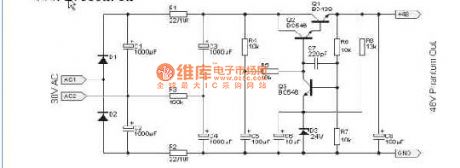
The electronic filter circuit diagram for microphone power supply
Published:2011/8/24 2:27:00 Author:Jessie | Keyword: Microphone power supply, electronic filter
View full Circuit Diagram | Comments | Reading(747)
Sallen - Key specific filter circuit diagram
Published:2011/8/19 2:08:00 Author:Jessie | Keyword: Sallen - Key, specific filter
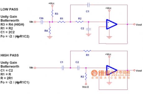
This circuit is an unity-gain circuit, which canchange gain of the filter Sallen - Keyand theamplitude-frequency characteristics and types of filter. In fact, Sallen - Key specific filter isa butterworth filterwith thegain in 1. (View)
View full Circuit Diagram | Comments | Reading(1193)
RC bridge oscillating circuit with regulating ring
Published:2011/8/19 2:28:00 Author:Jessie | Keyword: RC bridge oscillating, regulating ring

Connectingregulating ring to circuit, and adjusting potentiometer Rp, then you can use an oscilloscope to observe the output wave of oscillator circuit and the change of oscillating circuit's output wave, we will realize the influence of stability of regulating ring to sinusoidal oscillator circuit performance. (View)
View full Circuit Diagram | Comments | Reading(715)
Infrared transmitting and receiving circuit diagram
Published:2011/10/17 2:11:00 Author:Ecco | Keyword: Infrared transmitting , receiving

View full Circuit Diagram | Comments | Reading(742)
8038 general signal generator circuit diagram
Published:2011/10/17 1:36:00 Author:Ecco | Keyword: general signal generator

View full Circuit Diagram | Comments | Reading(2082)
Flash alarm circuit diagram
Published:2011/9/15 22:36:00 Author:Rebekka | Keyword: Flash alarm

When people reach the safe or other metal objects, in order to get the photo of people, the sensor circuit will send a pulse to the warning circuit. Its positive edge will start work around semiconductor silicon-controlled rectifier and GE flash tube to drive the camera. (View)
View full Circuit Diagram | Comments | Reading(988)
CXA1019S frequency regulation amplitude modulation radio circuit diagram
Published:2011/9/14 22:38:00 Author:Rebekka | Keyword: frequency regulation, amplitude modulation

CXA1019 is Japanese SONY company'shigh-performance, high-sensitivity dedicated FM radio Manifold AM. CXA1019 high integration includes FM / AM tuner circuit, mixer circuit, squelch circuit, power amplifier (power is between0.5 ~ 1W), DC voltage control volume, instructions and other tuned circuit. It can complete all the basic functions of the radio. Because of its low cost, superior performance, it is widely used in a variety of portable radios and electronic products.
(View)
View full Circuit Diagram | Comments | Reading(7575)
Three-phase three-wire system open phase protection circuit diagram
Published:2011/9/15 1:26:00 Author:Rebekka | Keyword: Three-phase three-wire system , open phase protection
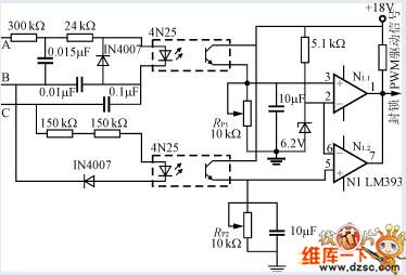
This is an openphase protection circuit for three-phase three-wire power supply. A, B, C are lack of any one phase, the optocoupler output level is lower than the inverting input of the comparator reference voltage. The comparator outputs low blockade PWM to drive signal, turn off the power.As well as the polarity of the comparator input changes, PWM signals can be blocked with a high level.
(View)
View full Circuit Diagram | Comments | Reading(2108)
AM synchronous detection circuit diagram
Published:2011/9/14 22:37:00 Author:Rebekka | Keyword: AM synchronous detection circuit

For wide range input signal level, it needs to use the synchronous detection circuit shown in the figure 16-1 if you want to get linear detector output. First it uses PLLICNE565 to make a moving signal that is the same with input signal n/2. Then it uses multiplier ICMC1496 and phase shift signalling to switch the input signal. After full-wave rectification, it can get detected output signal, moreover, because the rectification action works with input signal, the detected circuit has frequency selectivity.
(View)
View full Circuit Diagram | Comments | Reading(3566)
Indirect self-excited feedback astable multivibrator circuit composed of 555
Published:2011/8/23 21:10:00 Author:Ecco | Keyword: Indirect self-excited feedback , astable multivibrator , 555


View full Circuit Diagram | Comments | Reading(658)
Generator circuit of 555 square wave and sawtooth wave
Published:2011/9/18 22:06:00 Author:Ecco | Keyword: 555 , square wave , sawtooth wave, generator circuit
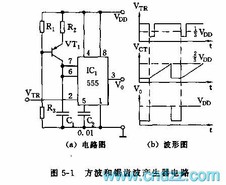
As shown in Figure 5-1, 555 and R2, C1, VT1 form a monostable trigger circuit, and the difference from the general flip-flop is that VT1, R1, R2, R3 form a constant current source, which charges for C1 to make a good voltage linearity, accurate delay. Delay time td = 1.1R2C1. If it requires trigger pulse period T to be greater than td, the output waveform is shown in Figure b.
(View)
View full Circuit Diagram | Comments | Reading(1453)
FM modulation circuit diagram using ceramic resonator
Published:2011/9/14 21:38:00 Author:Rebekka | Keyword: ceramic resonator, FM modulation

On frequency stability, the quartz crystal oscillator circuit is very advantageous, even the the VCXO circuit with large amount of frequency changing only changes about 1%, and the linear range of control voltage to frequency variation is not wide. Although the ceramic resonator Q value is lower than the quartz crystal oscillator, the inductive range is relatively broad, so it can get a wider frequency range, and the characteristics in the frequency stability is also better than the LC oscillator, so it is suitable for wideband FM modulator. (View)
View full Circuit Diagram | Comments | Reading(2949)
| Pages:53/195 At 204142434445464748495051525354555657585960Under 20 |
Circuit Categories
power supply circuit
Amplifier Circuit
Basic Circuit
LED and Light Circuit
Sensor Circuit
Signal Processing
Electrical Equipment Circuit
Control Circuit
Remote Control Circuit
A/D-D/A Converter Circuit
Audio Circuit
Measuring and Test Circuit
Communication Circuit
Computer-Related Circuit
555 Circuit
Automotive Circuit
Repairing Circuit