
Signal Processing
Index 48
First-order active phase-shift oscillator
Published:2011/11/21 2:21:00 Author:Ecco | Keyword: First-order, active , phase-shift oscillator

View full Circuit Diagram | Comments | Reading(640)
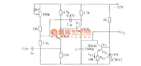
Tuning fork oscillator
Published:2011/11/21 2:20:00 Author:Ecco | Keyword: Tuning fork oscillator


Figure (a) uses regulator circuit D1 tolimit amplitute, and theinput and output phase-shift tuning fork is 180o.Figure (b)uses transistor saturation tolimit amplitute, and the transistor inverting in 180o.
(View)
View full Circuit Diagram | Comments | Reading(1279)
The frequency of XOR gate controlled oscillator
Published:2011/11/22 2:24:00 Author:Ecco | Keyword: XOR gate , controlled oscillator

View full Circuit Diagram | Comments | Reading(1323)
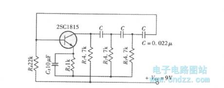
The example of phase-shift oscillator circuit
Published:2011/11/22 2:20:00 Author:Ecco | Keyword: phase-shift oscillator
View full Circuit Diagram | Comments | Reading(1149)
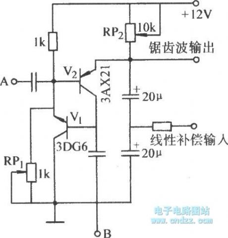
The sawtooth circuit using transistor as a constant current source
Published:2011/11/22 20:46:00 Author:Ecco | Keyword: sawtooth circuit , transistor , constant current source

View full Circuit Diagram | Comments | Reading(1857)
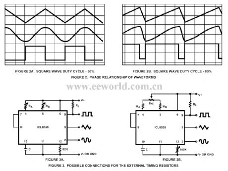
Universal signal generator with 8038
Published:2011/11/10 20:47:00 Author:Ecco | Keyword: Universal signal generator
View full Circuit Diagram | Comments | Reading(1987)
The self-excited sawtooth circuit using transistor to replace RD
Published:2011/11/22 21:01:00 Author:Ecco | Keyword: self-excited sawtooth , transistor , replace, RD
View full Circuit Diagram | Comments | Reading(666)
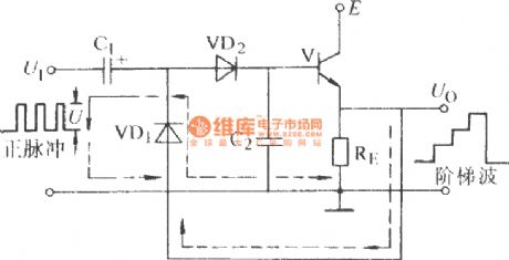
Bootstrap step wave circuit
Published:2011/11/22 21:01:00 Author:Ecco | Keyword: Bootstrap step wave
View full Circuit Diagram | Comments | Reading(700)
Bootstrap compensation sawtooth circuit
Published:2011/11/21 2:24:00 Author:Ecco | Keyword: Bootstrap compensation sawtooth
View full Circuit Diagram | Comments | Reading(1114)
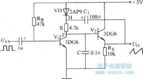
The lkHz Quick Start gating circuit using phase-shift oscillator
Published:2011/11/22 21:10:00 Author:Ecco | Keyword: lkHz , Quick Start , gating circuit, phase-shift oscillator

View full Circuit Diagram | Comments | Reading(796)
Distortional capacitor negative feedback sawtooth circuit
Published:2011/11/22 21:08:00 Author:Ecco | Keyword: Distortional, capacitor negative feedback, sawtooth circuit
View full Circuit Diagram | Comments | Reading(3838)
50kHz Meacham Eminem Mitch bridge oscillator
Published:2011/11/22 2:25:00 Author:Ecco | Keyword: 50kHz , Meacham Eminem , Mitch , bridge oscillator

View full Circuit Diagram | Comments | Reading(1072)
400Hz signal source
Published:2011/11/21 1:40:00 Author:Ecco | Keyword: 400Hz signal source
View full Circuit Diagram | Comments | Reading(655)
0.2 ~ 20000Hz voltage controlled ramp signal generator
Published:2011/11/21 1:40:00 Author:Ecco | Keyword: 0.2 ~ 20000Hz, voltage controlled , ramp , signal generator
View full Circuit Diagram | Comments | Reading(1098)
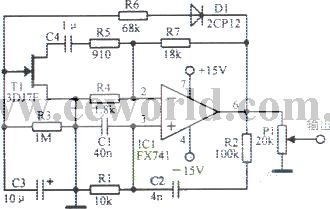
A multi-purpose signal generator circuit
Published:2011/11/21 1:30:00 Author:Ecco | Keyword: multi-purpose signal generator
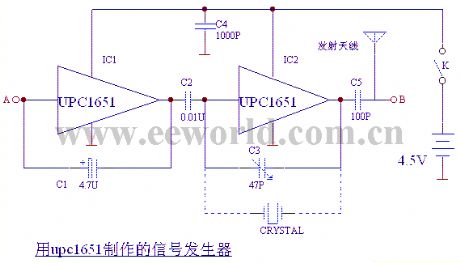
The circuit is shown as the chart, IC1, C1 form the oscillator with frequency being 400HZ; IC2, C3 form the 37MHZ about high-frequency oscillator ; the low-frequency signal output from the C2 can make modulation for high-frequency signal. C4 and antenna constitute a launch system. High-frequency oscillator's harmonic can be used as the three channel receiver in the television(or other channel ), and it shows black and white stripe signal. Points A , B output signals , which are respectively used for the detection signal source for low-frequency channel and image. C3 can replace the quartz crystal to stabilize the oscillation frequency, and it is shown in dotted line. Frequency can be selected 465KHZ, 10.7KHZ, 6.5KHZ, 4.43MHZ, 37MHZ.
(View)
View full Circuit Diagram | Comments | Reading(987)
Astable flip-flop multivibrator circuit
Published:2011/11/21 1:14:00 Author:Ecco | Keyword: Astable flip-flop multivibrator

The two parts' components and model parameters correspond to the same time to get a 1:1 duty cycle square wave , and the frequency RB is Rb1 or Rb2 in the figure, the upper limited value Rb1 <0.5BRc1; Rb2 <0.5 BRc2. Here B is the transistor collector current amplification factor. The lower limited resistance Rb1> 10Rc1; Rb2> 10Rc2. In circuit, the rectangular wave's frequency is 10Hz.
(View)
View full Circuit Diagram | Comments | Reading(754)
Simultaneous adjustment sawtooth circuit
Published:2011/11/21 1:01:00 Author:Ecco | Keyword: Simultaneous adjustment sawtooth
View full Circuit Diagram | Comments | Reading(716)
Time scale sawtooth wave generating circuit
Published:2011/11/21 1:54:00 Author:Ecco | Keyword: Time scale , sawtooth wave generating
View full Circuit Diagram | Comments | Reading(729)
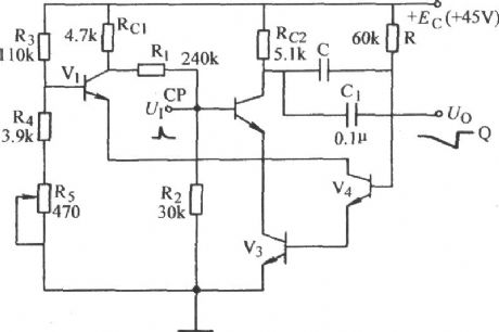
Rectangular liquid generator circuit diagram 1.9
Published:2011/11/21 0:55:00 Author:Ecco | Keyword: Rectangular liquid generator
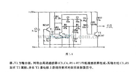
In the circuit , T1 and T2 form the inherent oscillator. T3 is the output stage . The network consists of high-pass filter (C3, C4, R6 + R7) and low-pass filter, and its output is added to T3 base by C6, R8, and it obtains the required rectangular wave oscillation signal on the collector of T3.
(View)
View full Circuit Diagram | Comments | Reading(601)
The sawtooth wave self-excitation circuit with adjustable frequency
Published:2011/11/21 1:53:00 Author:Ecco | Keyword: sawtooth wave , self-excitation , adjustable frequency
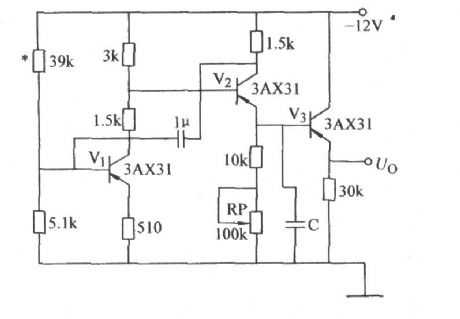
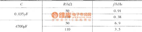
The relationship between sawtooth frequency f, capacitor C, resistor R is shown as the table. (View)
View full Circuit Diagram | Comments | Reading(687)
| Pages:48/195 At 204142434445464748495051525354555657585960Under 20 |
Circuit Categories
power supply circuit
Amplifier Circuit
Basic Circuit
LED and Light Circuit
Sensor Circuit
Signal Processing
Electrical Equipment Circuit
Control Circuit
Remote Control Circuit
A/D-D/A Converter Circuit
Audio Circuit
Measuring and Test Circuit
Communication Circuit
Computer-Related Circuit
555 Circuit
Automotive Circuit
Repairing Circuit