Signal Processing
A multi-purpose signal generator circuit
Published:2011/11/21 1:30:00 Author:Ecco | Keyword: multi-purpose signal generator | From:SeekIC

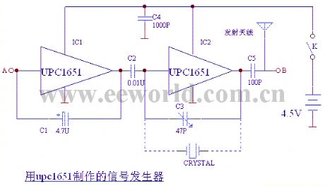
The circuit is shown as the chart, IC1, C1 form the oscillator with frequency being 400HZ; IC2, C3 form the 37MHZ about high-frequency oscillator ; the low-frequency signal output from the C2 can make modulation for high-frequency signal. C4 and antenna constitute a launch system. High-frequency oscillator's harmonic can be used as the three channel receiver in the television(or other channel ), and it shows black and white stripe signal. Points A , B output signals , which are respectively used for the detection signal source for low-frequency channel and image. C3 can replace the quartz crystal to stabilize the oscillation frequency, and it is shown in dotted line. Frequency can be selected 465KHZ, 10.7KHZ, 6.5KHZ, 4.43MHZ, 37MHZ.
Reprinted Url Of This Article:
http://www.seekic.com/circuit_diagram/Signal_Processing/A_multi_purpose_signal_generator_circuit.html
Print this Page | Comments | Reading(3)

Article Categories
power supply circuit
Amplifier Circuit
Basic Circuit
LED and Light Circuit
Sensor Circuit
Signal Processing
Electrical Equipment Circuit
Control Circuit
Remote Control Circuit
A/D-D/A Converter Circuit
Audio Circuit
Measuring and Test Circuit
Communication Circuit
Computer-Related Circuit
555 Circuit
Automotive Circuit
Repairing Circuit
Code: