
Signal Processing
Index 42
Simple sinusoidal oscillator circuit
Published:2011/10/27 21:13:00 Author:May | Keyword: sinusoidal oscillator

It can change the frequency range, and the oscillating signal is adjusted by potentiometer RP1. Since the output resistance is very low ( 1KΩ),it issuitable for various kinds of control circuit as a source.
In the circuit, the transistor's collector passesthrough R1, R2, C1, C2 to base to constitute feedback branch. Changing the device's parameters is OK.
(View)
View full Circuit Diagram | Comments | Reading(1891)
Threshold signal generator circuit using TcA965
Published:2011/10/27 21:19:00 Author:May | Keyword: Threshold signal generator

The circuit consists of multivibrator and threshold switch. The voltage of TCA965's pin 10 is decided by that of pin 6, pin 7, and pin 8, while the latter is determined by the bleeder R1~R4. The feedback is from pin 14 to pin 8 via R5. The unstable state occurs when the voltage of pin 9 is high enough. Then the circuit produces oscillation.
(View)
View full Circuit Diagram | Comments | Reading(2936)
50HZ time-base signal generator circuit diagram
Published:2011/10/26 21:57:00 Author:May | Keyword: 50HZ , time-base signal generator
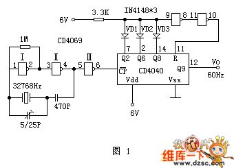
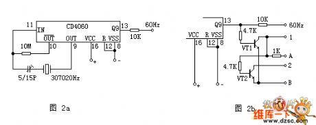
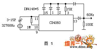
The attached figure 1 is the 60Hz digit-clock time-base circuit composed of the 12-bit binary serial counter/frequency divider CD4040 and six phase reverser CD4069 and so on. In the circuit, the CD4069's gate I and gate II constitute the crystal oscillator with oscillating frequency in 32768Hz. Chart 2a is another kind of 60Hz pulse generating circuit. It consists of the integrated circuit CD4060 and crystal oscillator with the resonance frequency in 30720Hz. CD4060 is 14-bit binary serial counter, frequency divider and oscillator. The CD4060's interior divides into two parts, one part is 14-level counter/frequency divider, and its frequency division coefficient is 16¯16348.
(View)
View full Circuit Diagram | Comments | Reading(8568)
The monostable multivibrator
Published:2011/11/22 21:52:00 Author:Ecco | Keyword: Monostable multivibrator

View full Circuit Diagram | Comments | Reading(874)
4GHZ oscillator circuit diagram composed of BFR34A transistor
Published:2011/12/8 20:21:00 Author:Ecco | Keyword: 4GHZ, oscillator, transistor

View full Circuit Diagram | Comments | Reading(1532)
Small electronic coupling oscillator circuit diagram
Published:2011/12/8 20:23:00 Author:Ecco | Keyword: Small , electronic coupling oscillator

View full Circuit Diagram | Comments | Reading(942)
45MHz FET oscillator circuit
Published:2011/11/28 0:57:00 Author:Ecco | Keyword: 45MHz , FET oscillator

The circuit's quartz crystal is between the source and drain of field effect transistor. The operating point is determined by the source resistor. Inductor and capacitor form a series resonant circuit.
(View)
View full Circuit Diagram | Comments | Reading(1647)
The crystal oscillator circuit with frequency in 2MHz
Published:2011/11/28 0:53:00 Author:Ecco | Keyword: crystal oscillator , 2MHz

Figure (a) and (b) show the two 2MHZ basic oscillator circuits. According to the circuit structure, it can adjust its best operating point by testing.
(View)
View full Circuit Diagram | Comments | Reading(2255)
Logarithmic sweep voltage controlled oscillator
Published:2011/11/28 0:31:00 Author:Ecco | Keyword: Logarithmic, sweep , voltage controlled oscillator

View full Circuit Diagram | Comments | Reading(1132)
The sine wave oscillator using LM386
Published:2011/11/24 20:49:00 Author:Ecco | Keyword: sine wave oscillator
The chart shows the sinusoidal oscillator circuit using LM386; the circuit uses the Wien bridge oscillator method, and the distortion factor of output signal of is very low. Small bulb H and resistor R3 form the negative feedback circuit, which makes sure that the signal amplitude output by oscillator is stable and has low distortion. When the capacitors C1, C2 values are the same , and they use the icon data, the sinusoidal frequency is 1KHz. When it is in actual production , H can select 3V, 15mA small bulb.
(View)
View full Circuit Diagram | Comments | Reading(2192)
Triangle wave - square wave generator circuit
Published:2011/11/24 20:53:00 Author:Ecco | Keyword: Triangle wave , square wave , generator
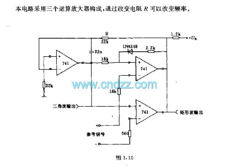
The circuit is composed of 3 operational amplifiers, and changing resistor R can change the frequency.
(View)
View full Circuit Diagram | Comments | Reading(1276)
Parallel resonant crystal oscillator composed of Gate circuit
Published:2011/11/27 20:28:00 Author:Ecco | Keyword: Parallel resonant , crystal oscillator , Gate circuit

When the quartz crystal under the action of the applied voltage, it will produce a piezoelectric effect, then the quartz crystal produces the mechanical vibrations, when the frequency of the applied voltage and crystal's natural oscillation is the same, the crystal 's mechanical amplitude is the largest and the alternating electric field will be largest to form piezoelectric resonator. The reactance frequency characteristics of quartz crystal reactance show that it has two closed resonance volume ratio, one is the series resonant frequency , the other one is parallel resonant frequency , when the crystal is in series resonance, the reactance is minimum, when it is in parallel resonance, the reactance is maximum, when it is between two frequency ranges, the crystal shows inductive , when it is free from two frequency ranges, the crystal shows capacitive.
(View)
View full Circuit Diagram | Comments | Reading(3455)
The pulse generator circuit with sharp pulse and sawtooth pulse
Published:2011/11/27 21:05:00 Author:Ecco | Keyword: pulse generator , sharp pulse , sawtooth pulse

The upper limit of the two pulses' frequency generated by the gate circuit is 5MHZ, the lower limit depends on the size of the capacitor . Sharp pulse width is about 50ns, which is output directly from TTL and non gate; sawtooth pulse is generated by impedance converter, which is a Schmitt trigger with high input impedance, so that it has a good sawtooth linearity . Gate device substitution : FLH731-49713S, FLH491-49702.
(View)
View full Circuit Diagram | Comments | Reading(969)
The pulse generator ( Figure 1.6 ) circuit with output multiple waveforms
Published:2011/11/27 20:49:00 Author:Ecco | Keyword: pulse generator , multiple waveforms

It uses the programmable unijunction transistor Th to form a pulse waveform generator circuit which can output multiple waveforms. Figure (b) shows the pulse waveforms output by a, b, c, d points which are shown in Figure (a) circuit. In this case, UB = 50V, pulse frequency f = 1000Hz, pulse peak U = UP = 20V. Component parameters R1 = 0.164MΩ, R2 = 0.256MΩ, R3 = 4.9MΩ, R4 or R5 = 8Ω, C = 410pF.
(View)
View full Circuit Diagram | Comments | Reading(1630)
The crystal oscillator with switch
Published:2011/11/24 21:30:00 Author:Ecco | Keyword: crystal oscillator , switch

View full Circuit Diagram | Comments | Reading(796)
Adjustable crystal oscillator
Published:2011/11/24 21:30:00 Author:Ecco | Keyword: Adjustable crystal oscillator

View full Circuit Diagram | Comments | Reading(823)
Crystal l00kHz interval calibration oscillator
Published:2011/11/27 20:42:00 Author:Ecco | Keyword: Crystal , l00kHz , interval calibration , oscillator

View full Circuit Diagram | Comments | Reading(674)
Transistor- FET transistor oscillator
Published:2011/11/27 20:41:00 Author:Ecco | Keyword: Transistor, FET transistor , oscillator

View full Circuit Diagram | Comments | Reading(988)
The audio signal generator circuit with low output resistance
Published:2011/11/28 21:01:00 Author:Ecco | Keyword: audio signal generator, low output resistance
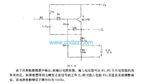
As it is output from the emitter follower, the output resistance is very low. Output voltage can be decided by R1, R2 piezoelectric resistance. If you want to get sinusoidal signal without distortion, you can access resistor R3, its value is determined by the test adjustment. In the case of parameters, the frequency of the circuit is about 500Hz.
(View)
View full Circuit Diagram | Comments | Reading(1141)
Rectangular wave generator ( Figure 1.9 ) circuit
Published:2011/11/28 20:54:00 Author:Ecco | Keyword: Rectangular wave generator
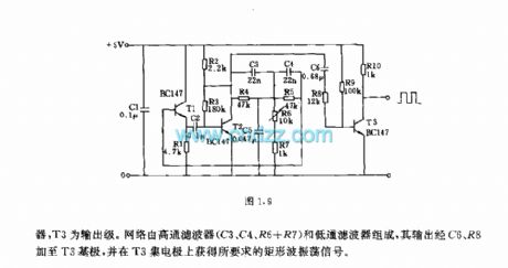
In the circuit, T1, T2 form the oscillator, and T3 is the output stage. Network consists of high-pass filter (C3, C4, R6 + R7) and low-pass filter. Its output is added to T3 base by C6, R8 to get the required rectangular wave oscillation signal collector of T3.
(View)
View full Circuit Diagram | Comments | Reading(630)
| Pages:42/195 At 204142434445464748495051525354555657585960Under 20 |
Circuit Categories
power supply circuit
Amplifier Circuit
Basic Circuit
LED and Light Circuit
Sensor Circuit
Signal Processing
Electrical Equipment Circuit
Control Circuit
Remote Control Circuit
A/D-D/A Converter Circuit
Audio Circuit
Measuring and Test Circuit
Communication Circuit
Computer-Related Circuit
555 Circuit
Automotive Circuit
Repairing Circuit