Position: Home > Circuit Diagram > Signal Processing > Generator circuit of 555 square wave and sawtooth wave
Signal Processing
Generator circuit of 555 square wave and sawtooth wave
Published:2011/9/18 22:06:00 Author:Ecco | Keyword: 555 , square wave , sawtooth wave, generator circuit | From:SeekIC

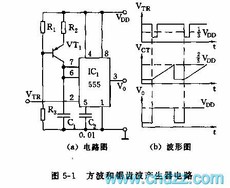
As shown in Figure 5-1, 555 and R2, C1, VT1 form a monostable trigger circuit, and the difference from the general flip-flop is that VT1, R1, R2, R3 form a constant current source, which charges for C1 to make a good voltage linearity, accurate delay. Delay time td = 1.1R2C1. If it requires trigger pulse period T to be greater than td, the output waveform is shown in Figure b.
Reprinted Url Of This Article:
http://www.seekic.com/circuit_diagram/Signal_Processing/Generator_circuit_of_555_square_wave_and_sawtooth_wave.html
Print this Page | Comments | Reading(3)

Article Categories
power supply circuit
Amplifier Circuit
Basic Circuit
LED and Light Circuit
Sensor Circuit
Signal Processing
Electrical Equipment Circuit
Control Circuit
Remote Control Circuit
A/D-D/A Converter Circuit
Audio Circuit
Measuring and Test Circuit
Communication Circuit
Computer-Related Circuit
555 Circuit
Automotive Circuit
Repairing Circuit
Code: