Signal Processing
Ladder wave generation circuit
Published:2011/8/29 1:37:00 Author:TaoXi | Keyword: Ladder wave, generation circuit | From:SeekIC

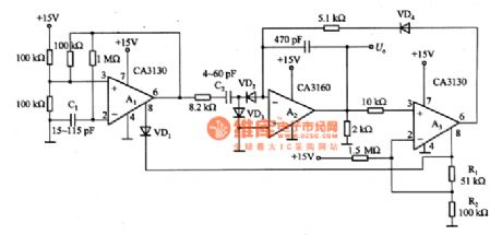
The ladder wave generation circuit is as shown in the figure. In this circuit, the A1 is the multivibrator which produces the square wave, and it is controlled by the 8-pin of the selective passing port. A2 is the integrator, the output of it is the ladder wave, the operating state of it is controlled by the delay switch. A3 is the delay amplifier, it makes the output of selective passing port's 8-pin divide by R1 and R2, and it adds the positive feedback to pin-2 to make it have the delay characteristic. The C1 can be used to adjust the frequency of the multivibrator, the C2 can be used to adjust the stepping height, the VD1 can be used to prevent the reversal of the multivibrator, VD2 and VD3 are the charging commutation circuit.
Reprinted Url Of This Article:
http://www.seekic.com/circuit_diagram/Signal_Processing/Ladder_wave_generation_circuit.html
Print this Page | Comments | Reading(3)

Article Categories
power supply circuit
Amplifier Circuit
Basic Circuit
LED and Light Circuit
Sensor Circuit
Signal Processing
Electrical Equipment Circuit
Control Circuit
Remote Control Circuit
A/D-D/A Converter Circuit
Audio Circuit
Measuring and Test Circuit
Communication Circuit
Computer-Related Circuit
555 Circuit
Automotive Circuit
Repairing Circuit
Code: