Signal Processing
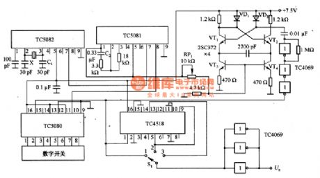
PLL pulse generator circuit composed of the TC5082
Published:2011/8/28 20:32:00 Author:TaoXi | Keyword: PLL, pulse, generator circuit | From:SeekIC

The PLL pulse generator circuit which is composed of the TC5082 is as shown in the figure. In this circuit, the x is the l0.24MHZ crystal oscillator, you can get the 10kHz reference frequency through the TC5082, and you can use the C1 to adjust the reference frequency. VT1~VT4 are the voltage-controlled oscillator, it is designed as the emitter coupling multivibrator, you can change the value of RP1 to make it oscillate in the range of 100~990kHZ. The output of the voltage-controlled oscillator is amplified by the TC4069, the amplified signal adds to the clock input port of the TC5080 (pin-15). The frequency divider circuit uses the TC4518, the output port has the buffer which is composed of the three inverter of the TC4069, the purpose of the parallel connection is to improve the driving capability.
Reprinted Url Of This Article:
http://www.seekic.com/circuit_diagram/Signal_Processing/PLL_pulse_generator_circuit_composed_of_the_TC5082.html
Print this Page | Comments | Reading(3)

Article Categories
power supply circuit
Amplifier Circuit
Basic Circuit
LED and Light Circuit
Sensor Circuit
Signal Processing
Electrical Equipment Circuit
Control Circuit
Remote Control Circuit
A/D-D/A Converter Circuit
Audio Circuit
Measuring and Test Circuit
Communication Circuit
Computer-Related Circuit
555 Circuit
Automotive Circuit
Repairing Circuit
Code: