Signal Processing
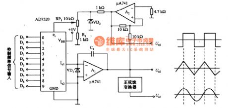
Function generator circuit composed of the AD7520
Published:2011/8/28 22:40:00 Author:TaoXi | Keyword: Function generator | From:SeekIC


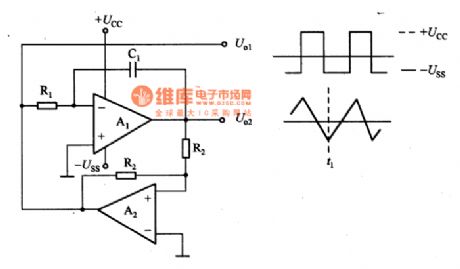
The function generator circuit which is composed of the AD7520 is as shown in the figure. The function generator basic circuit which is as shown in figure 6-37(a) is composed of the integrator A1 and the comparator A2. In the moment of T1, if the output of A2 reaches the negative saturation voltage-Uss, the output of A1 will be U. When 1+U2=0, the output of A2 will reverse, the -Uss will change into the +Ucc, the output of A1 will decrease to U. When 1+U2=0, it will reverse again. The circuit will produce the oscillation, the time constant is decided by the T=R1C1. So we can control the frequency oscillation by changing the value of R1.
Reprinted Url Of This Article:
http://www.seekic.com/circuit_diagram/Signal_Processing/Function_generator_circuit_composed_of_the_AD7520.html
Print this Page | Comments | Reading(3)

Article Categories
power supply circuit
Amplifier Circuit
Basic Circuit
LED and Light Circuit
Sensor Circuit
Signal Processing
Electrical Equipment Circuit
Control Circuit
Remote Control Circuit
A/D-D/A Converter Circuit
Audio Circuit
Measuring and Test Circuit
Communication Circuit
Computer-Related Circuit
555 Circuit
Automotive Circuit
Repairing Circuit
Code: