Signal Processing
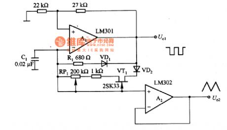
Sawtooth wave generating circuit composed of the LM301
Published:2011/8/28 23:03:00 Author:TaoXi | Keyword: Sawtooth wave, generating circuit | From:SeekIC

The sawtooth wave generating circuit which is composed of the LM301 is as shown in the figure. The timing resistor of the multivibrator is devided by VD1 and VD2, and it uses the charging and discharging voltage of C1 to produce the sawtooth wave. A1 is the level comparator, when the output of it is positive, the VD1 cuts off, the VD2 conducts, the current which is added to C1 is produced by the constant current source which is composed of VT1, so the voltage straights up. When the output of A1 is negative, the VD2 cuts off, the VD1 conducts, the timing resistor changes into R1, the fall time is less than the rise time. The voltage of C1 is the sawtooth wave voltage, it is output by the buffer amplifier A2.
Reprinted Url Of This Article:
http://www.seekic.com/circuit_diagram/Signal_Processing/Sawtooth_wave_generating_circuit_composed_of_the_LM301.html
Print this Page | Comments | Reading(3)

Article Categories
power supply circuit
Amplifier Circuit
Basic Circuit
LED and Light Circuit
Sensor Circuit
Signal Processing
Electrical Equipment Circuit
Control Circuit
Remote Control Circuit
A/D-D/A Converter Circuit
Audio Circuit
Measuring and Test Circuit
Communication Circuit
Computer-Related Circuit
555 Circuit
Automotive Circuit
Repairing Circuit
Code: