Signal Processing
Sawtooth wave generating circuit composed of the LM747
Published:2011/8/14 19:45:00 Author:TaoXi | Keyword: Sawtooth wave, generating | From:SeekIC

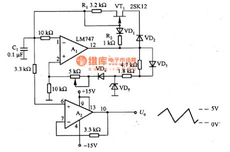
The sawtooth wave generating circuit which is composed of the LM747 is as shown in the figure. It uses the self-excited multivibrator to produce the sawtooth wave. In order to make the capacitance C1's chargig voltage line increase linearly, we use the constant current source which is composed of the VT1 and R1. And in order to reduce return time of the sawtooth wave, the VD1 and R2 supply the discharging circuit which has very small discharge time constant. The voltage-regulator diode VD5 clamps the output of A1 to stabilize the output amplitude of it. When the C1 is discharging, if you supply the reverse bias to the VD5, the VD4 will cut off, the in-phase input port of A1 is 0V, the minimum level of the sawtooth wave goes back to 0V.
Reprinted Url Of This Article:
http://www.seekic.com/circuit_diagram/Signal_Processing/Sawtooth_wave_generating_circuit_composed_of_the_LM747.html
Print this Page | Comments | Reading(3)

Article Categories
power supply circuit
Amplifier Circuit
Basic Circuit
LED and Light Circuit
Sensor Circuit
Signal Processing
Electrical Equipment Circuit
Control Circuit
Remote Control Circuit
A/D-D/A Converter Circuit
Audio Circuit
Measuring and Test Circuit
Communication Circuit
Computer-Related Circuit
555 Circuit
Automotive Circuit
Repairing Circuit
Code: