About SeekIC | Services | Payment | Advertisements service | Contact Us | Links
© 2008-2012 SeekIC.com Corp.All Rights Reserved.

Published:2009/6/19 4:21:00 Author:May
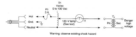
Very often a power transformer is suspect and connecting a shorted transformer to an ac source can be hazardous. This test method will detect a defective or shorted transformer. The primary of the power transformer is energized through a Variac (0 to 130 Vac) and a lamp equal in wattage to about half that of the transformer under test. Connect the transformer, set Variac at zero, then energize cir-cuit. Apply voltage to suspected transformer (Tx) as shown. The lamp should not light. If it does, Tx is shorted. Next, short the secondary of suspected Tx. This time, the lamp should light. For multiple winding transformers, repeat for each secondary winding. Beware of the shock hazard as the open windings of Tx can develop full-rated voltage. (View)
View full Circuit Diagram | Comments | Reading(552)
Published:2009/6/19 4:17:00 Author:May
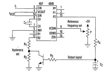
Comparison of an input signal's frequency (fi) with that of voltage-controlled oscillator (fVCO) can be accomplished with just one CMOS phase-locked loop IC and a transistor (see figure). The phase and the frequency can be compared with a phase comparator, which, along with the VCO, is part of the HEF4046 PLL IC. The transistor helps introduce hysteresis, enabling the circuit to be used as a switch driver. (View)
View full Circuit Diagram | Comments | Reading(2276)
Published:2009/6/19 4:14:00 Author:May
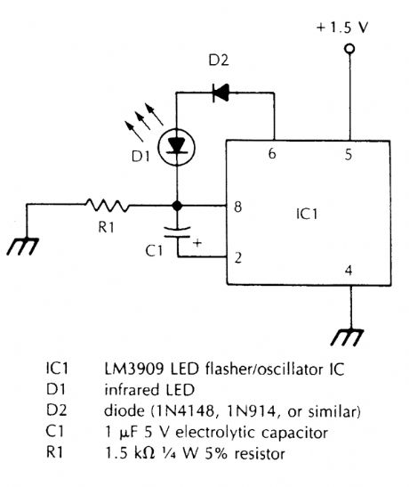
This oscillator pulses an IR LED at about 1000 Hz. It should be useful as a test for lining up IR communications links or setting up fiber-optic cables, etc. (View)
View full Circuit Diagram | Comments | Reading(599)
Published:2009/6/19 4:14:00 Author:May
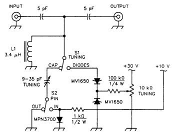
A loosely coupled tuned circuit for testing IMD production by PIN and tuning diodes in a narrow-band preselector, S1, TUNING, selects whether C1 or a pair of back-to-back MV1650 tuning diodes resonate L1. S2, PIN, adds or removes an MPN3700 PIN diode in series with C1. L1 consists of 33 turns of #28 enameled wire on a t-37-6 toroidal powdered-iron core. The MV1650, a 20-V tuning diode, exhibits a nominal capacitance of 100 pF at a tuning voltage of 4V. (View)
View full Circuit Diagram | Comments | Reading(903)
Published:2009/6/19 4:13:00 Author:May

XTAL1 drives amplifjer Q3/Q4, which is tuned to 2.25 MHz. The detected signal is fed to audio amp!ifier IC1. A 9-V supply is used. The circuit operates at 2.25 MHz and is designed to be used with an ultrasonic sound transmitter at this frequency. (View)
View full Circuit Diagram | Comments | Reading(903)
Published:2009/6/19 4:13:00 Author:May
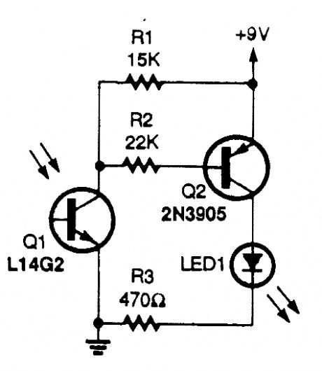
The circuit uses an IR phototransistor, Q1, to detect a remote control's IR output signal. A PNP transistor, Q2, then amplifies Q1's output and lights LED1. That indicates that an infrared signal has been detected by the phototransistor, or in other words, that your remote control works. (View)
View full Circuit Diagram | Comments | Reading(1749)
Published:2009/6/19 4:12:00 Author:May

This circuit uses a pyroelectric detector to detect IR emissions in the 6- to 14-micron range. It is useful for security or infrared experiments. PYR1 is a pyroelectric IR detector. The unit should be mounted in a case with an IR lens to focus energy on the detector. (View)
View full Circuit Diagram | Comments | Reading(2246)
Published:2009/6/19 4:09:00 Author:May

The transmitter has a VXO circuit to drive an amplifier that is keyed. The keyed amplifier drives an MRF 476 final amplifier, which delivers about 2-W output. A solid-state T-R switch is included for the receiver. The parts values shown are for the 20-me-ter band. (View)
View full Circuit Diagram | Comments | Reading(1376)
Published:2009/6/19 4:04:00 Author:May
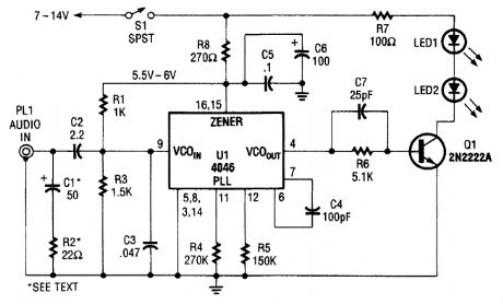
Audio input from PL1 frequency modulates the VCO section of a 4046 PLL chip. The VCO out-put drives Q1, a switching transistor. Q1 drives two IR LEDs. The signal produced is around 100 kHz, FM carrier VCO sensitivity is around 7.5 kHz/V. (View)
View full Circuit Diagram | Comments | Reading(4288)
Published:2009/6/19 4:03:00 Author:May

The 0-to 130-V voltmeter and neon AC PWR lamp provide an average indication of the ac power. The fuse and metal oxide varistor(MOV)protect the monitor against overvoltage spikes.Four 1N4004 diodes rectify the ac voltage, generating negative-going pulses twice per cycle(every 8.33 ms for 60-Hz power). Variable-resistor F1 supplies a reduced amplitude sample of these pulses to a missing pulse detector consisting of Q1, IC1, and associated circuitry. As long as the pulse amplitude exceeds the threshold value set by RI, IC1 continually triggers, keeping its output high.When the pulse amplitude drGps below the threshold value, IC1 times out with a time constant set by variable resistor R2 and the 0.47-μF capacitor. R2 is calibrated to read the number of cycles required for a dropout indication. It can be set between 1 cycle(about 17 ms)and 30 cycles(0.5 second).When IC1 times out, its output goes low. This turns on LED1. The low output also triggers IC2, which is configured as a set-reset flip-flop. This turns on LED2. When the voltage returns to normal, IC1 again starts triggering and its output returns high, turning off LED1. LED2, however, remains on until the manual reset button is pressed.The circuit is powered by a 9-V battery and is assembled in a plastic or grounded metal case. No-tice that thqre's no isolation between the ac power line and the monitor circuitry. Be careful to avoid electrical shock when testing the circuitry. (View)
View full Circuit Diagram | Comments | Reading(1625)
Published:2009/6/19 4:03:00 Author:May

An IR-detector circuit offers an audible (as well as a visual) output, and also stretches the on time of the detected pulse to make the output easier to see, as shown.Photoresistor Q1 detects a remote's IR output pulse and sends a negative-going pulse to the trig-ger input (pin) of the 555IC, U1. The 555 is connected in a one-shot timer circuit; the output (pin 3) on time is set by the values of C3, R3, and R5 When an input pulse is detected, pin 3 goes high, lighting LED1 and activating the piezo buzzer, BZ1.For longer output pulses, set R5 to its maximum resistance value. To lengthen the circuit's on-time range, increase the value of C3, and to shorten the on-time range lower the value of C3. (View)
View full Circuit Diagram | Comments | Reading(979)
Published:2009/6/19 3:55:00 Author:May


The personal message recorder is built around an ISD1016 CMOS voice messaging system, which does away with the cumbersome and expensive analog-to-digital and digital-to-analog con-version circuits.
A functional block diagram of the ISD1016 is shown. The ISD1016 contains all of the functions necessary for a complete message-storage system. The preamplifier stage accepts audio signals di-rectly from an external microphone and routes the signals to the ANA OUT (analog out) terminal. An automatic-gain control (AGC) dynamically adjusts the preamplifier gain to extend the input signal range. Together, the preamp and ACrC circuits provide a maximum gain of 24 dB. The internal clock samples the signal and, under the control of the address-decoding logic, writes the sampling to the analog-storage array. Eight external input lines allow the ISD1016's message space to be addressed in 160 equal segments, each with a 100-millisecond duration. When all address lines are held low, the storage array can hold a single, continuous, 16-second message.
However, there is a special addition to the POWER DOWN input (pin 24) of UI. If the internal mem-ory becomes full during recording, an overflow condition is generated in order to trigger the next de-vice. Once an overflow occurs, pin 24 must be taken high and then low again before a new playback of record operation can be started.
Transistor Q1, C3, R5, and R6 form a one-shot pulse generator that automatically clears any overflow condition each time that start switch (51) is pressed. Switch 52 selects either the playback or the record mode. Switch 54-an 8-position (a-h) DIP switch-is included in the circuit to allow the circuit's record/playback time to be varied from 0 to 16 seconds. The maximum time available is when al18 switch positions are closed (or set to the on position). Resistor network R8 (a-h) is in-cluded in the circuit to provide a pull-up function for the address lines, which thereby controls UI's record/playback time. (View)
View full Circuit Diagram | Comments | Reading(2026)
Published:2009/6/19 3:53:00 Author:May

Sensor SEN1 outputs a dc voltage that varies linearly with relative humidity. This dc voltage is fed through R1 and R2 to A/D converter chip U2. Zero set is performed with R4. The LCD display is calibrated with R7 to read 0 to 100 percent. (View)
View full Circuit Diagram | Comments | Reading(1322)
Published:2009/6/19 3:52:00 Author:May

A portable light-level meter with a five-decade dynamic range is shown. The circuit is calibrated at mid-range with the appropriate illumination by adjusting R2 such that the amplifier output equals the reference and the meter is at center scale. The emitter-base voltage of Q22 will vary with supply voltage; so R4 is included to minimize the effect on circuit balance. If photocurrents less than 50 nA are to be measured, it is necessary to compensate the bias current of the op amp.The logging slope is not temperature compensated. With a five-decade response, the error at the scale extremes will be about 40% (a half stop in photography) for a ±18℃ temperature change.If temperature compensation is desired, it is best to use a center-zero meter to introduce the off-set, rather than the reference compensation. It can be obtained by making the resistor in series with the meter a copper wire-wound unit.If this design is to be used for photography, it is important to remember that silicon photodiodes are sensitive to near-infrared light, whereas ordinary film is not. Therefore, an infrared-stop filter is called for. A blue-enhanced photodiode or an appropriate correction filter would also produce best results. (View)
View full Circuit Diagram | Comments | Reading(542)
Published:2009/6/19 3:51:00 Author:May
Some oil-fired systemt use threewire thermostats to control the operation of the burner motor and ignition system by activaring a relay. This is a typical installation for such systems. (View)
View full Circuit Diagram | Comments | Reading(504)
Published:2009/6/19 3:51:00 Author:May

This circuit uses a Phillips capacitive humidity sensor that has a AC variation of 45 pF over 0 to 100 pf, RH. IC2 is an oscillator whose frequency is determined by the RH sensor, It is compared to fixed oscillator, and tie difference frequency is taken by IC3C and rectified, outputting a 0- to 1-V signal for RH between 0 and 100%. (View)
View full Circuit Diagram | Comments | Reading(1240)
Published:2009/6/19 3:49:00 Author:May

Electric-heuting systems that do not contain a low-current thermostat (as in the prerious installation), use a heavy-duty thermostut thtu directly feeds current to the heating element.For such systems, it will be necessary to install a heavy-duty relay (K1 in this exumple) to control the heavy heating-element current. (View)
View full Circuit Diagram | Comments | Reading(515)
Published:2009/6/19 3:47:00 Author:May

The analog first-response monitor is built around a pair of cross-coupled SCRs, each of which receives its gate trigger current from the anode of the other SCR. (View)
View full Circuit Diagram | Comments | Reading(678)
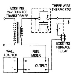
Published:2009/6/19 3:47:00 Author:May

This drawing shows the Fuel Miser connecled in series wlith the thermostat of a two-wire gas furnace that's powered by c 24-volt transformer. (View)
View full Circuit Diagram | Comments | Reading(582)
Published:2009/6/19 3:46:00 Author:May
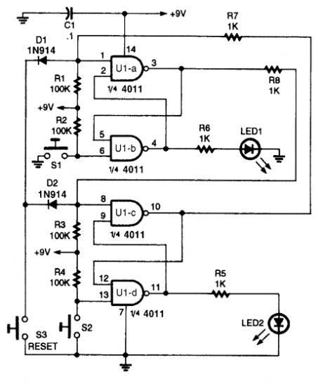
Two interlocking flip flops are used to detect the first of two inputs,but a logical-level signal can be substituted. (View)
View full Circuit Diagram | Comments | Reading(550)
| Pages:78/101 At 206162636465666768697071727374757677787980Under 20 |
Response in 12 hours
© 2008-2012 SeekIC.com Corp.All Rights Reserved.