
Measuring and Test Circuit
Index 75
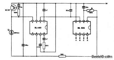
COMPACT_IR_RECEIVER
Published:2009/6/24 21:32:00 Author:May
View full Circuit Diagram | Comments | Reading(0)
ULTRASONIC_MOTION_DETECTOR
Published:2009/6/24 21:32:00 Author:May

A 567 PLL IC operates in a dual-function mode as a signal generator and an FM receiver. The 567's square-wave output at pin 5 is coupled to the base of Q1, and from Q1's emitter to the input of the power amplifier (Q2 and Q6). The output drives the piezo speaker, SPKR1.
The receive portion of the circuit operates as follows: transistors Q3 and Q4 are connected in a two-stage, high-gain, audio-frequency amplifier circuit, with the input connected to a second piezo speaker (SPKR2) operating as a sensitive microphone. The amplifier's output is coupled to the 567's input at pin 3. When an in-band signal is received, the LED lights.
The 567's FM output is coupled from pin 2 to the input of a very-low-frequency single-transistor amplifier, Q5. The amplifier's output at Q5's collector drives a voltage-doubler circuit (C11, D1, D2, and C12). The dc output feeds a 0- to 1-mA analog meter.
By placing the two pigzo speakers one foot apart and aiming them in the same direction, toward a nonmoving solid object, the signal from the transmitter's speaker urill reflect back into the receiver's speaker, and the frequency at the 567's input will be the same as the one being transmitted.
The ac output at pin 2 is zero when the outgoing and incoming frequencies are the same. How-ever, when the signal is reflected from a moving object, the received frequency will be either lower or higher than the transmitted one. If the object is moving away from the speakers, the received fre-quency will be lower; if the object is moving toward the speakers, the frequency will be higher.
The pin-2 signal is fed through a 470-pF capacitor to the base of Q5, where the signal is ampli-fied and fed to a voltage doubler, and then on to a meter circuit.
If you wish, the voltage doubter and meter can be removed and replaced with headphones connected between the negative side of C11 and circuit ground. That will allow you to listen to the difference-frequency signal as objects move in front of the speakers. (View)
View full Circuit Diagram | Comments | Reading(0)
ULTRASONIC_REMOTE_CONTROL_TESTER
Published:2009/6/24 21:27:00 Author:May
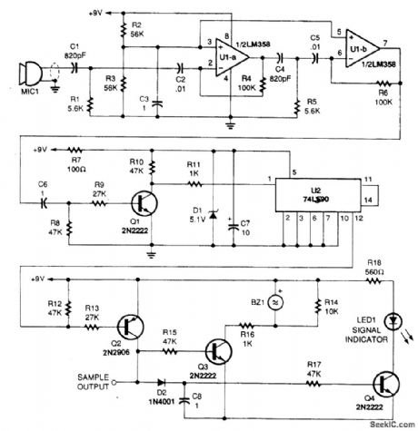
This circuit picks up the ultrasonic tone via MIC1, amplifies it, and divides it by 10 in IC U2, a 74LS90. The output of U2 drives an audio amplifier and a piezoelectric element is used as a speaker. (View)
View full Circuit Diagram | Comments | Reading(0)
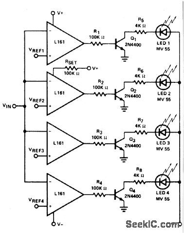
WOLTAGE_LEVEL_DETECTOR
Published:2009/6/24 21:26:00 Author:May
View full Circuit Diagram | Comments | Reading(589)
1IONIZATION_CHAMBER_SMOKE_DETECTOR
Published:2009/6/24 21:20:00 Author:May
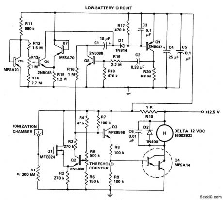
If the smoke alarm signal must be a continuous one rather than pulsating, then the slightly less expensive, all discrete transistor version of the MC14572 may be used. (View)
View full Circuit Diagram | Comments | Reading(0)
IONIZATION_CHAMBER_SMOKE_DETECTOR
Published:2009/6/24 21:15:00 Author:May

Battery-operated, ionization chamber smoke detector includes a circuit to generate a unique alarm when the battery reaches the end of its useful life. The circuit uses the MCMOS MC14572 for two alarm oscillators (smoke and low battery). This circuit additionally uses five discrete transistors as buffers and comparators. (View)
View full Circuit Diagram | Comments | Reading(0)
GAS_AND_SMOKE_DETECTOR
Published:2009/6/24 21:13:00 Author:May
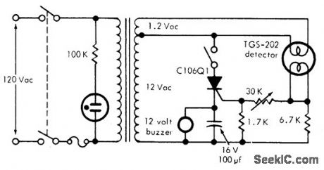
This circuit can detect smoke and a number of gases (CO, CO2, methane, coal gas and others) with a 10 ppm sensitivity. It uses a heated surface semiconductor sensor. Detection occurs when the gas concentration in-crease causes a decrease of the sensor element internal resistance. The switch in series with the SCR is used for resetting the alarm. (View)
View full Circuit Diagram | Comments | Reading(0)
OPTOELECTRONIC_PYROMETER
Published:2009/6/24 4:19:00 Author:May

This setup optically measures the temperature of an incandescent body. It makes use of the shift in the emission spectrum of a black body toward shorter wavelengths, as temperature is increased.Optical ffiters are used to split the emission spectrum, with one photodiode being illuminated by short wavelengths (visible light) and the other by long (infrared). The photocurrents are converted to logarithms by Q1 and Q2. These are subtracted to generate an output that varies as the log of the ratio of the illumination irttensiftes. Thus, the circuit is sensitive to changes in spectral distribution, but not intensity. (View)
View full Circuit Diagram | Comments | Reading(0)
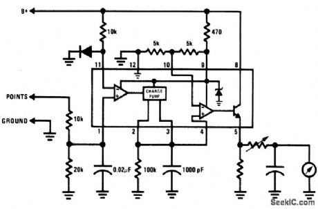
BREAKER_POINT_DWELL_METER
Published:2009/6/24 4:19:00 Author:May
View full Circuit Diagram | Comments | Reading(988)
15_V_ELECTRONIC_THERMOMETER
Published:2009/6/24 4:11:00 Author:May
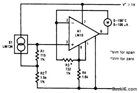
An electronic thermometer design, useful in the range of -55℃ to 150'℃, is shown. The sensor, S1, develops a current that is proportional to absolute temperature. This is given the required offset and range expansion by the reference and op amp, resulting in a direct readout in either ℃ or °F. (View)
View full Circuit Diagram | Comments | Reading(543)
CENTIGRADE_THERMOMETER_WITH_COLD_JUNCTION_COMPENSATION
Published:2009/6/24 4:10:00 Author:May
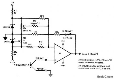
This electronic thermometer has a 10-mV/'C output from 0'C to 1300'℃. The trimming proce-dure is as follows: first short out the LM329B, the LM335 and the thermocouple. Measure the output voltage (equal to the input offset voltage times the voltage gain). Then apply a 50-mV input voltage and adjust the GAIN ADJUST pot until the output voltage is 12.25 V above the previously measured value. Next, short out the thermocouple again and remove the short across the LM335. Adjust the TC ADJUST pot so that the output equals 10 mV/°K times the absolute temperature. Finally, remove the short across the LM329B and adjust the ZER0 ADJUST pot so that the output voltage equals 10 mV/℃ times the ambient temperature in ℃. (View)
View full Circuit Diagram | Comments | Reading(0)
BARGRAPH_CAR_VOLTMETER
Published:2009/6/24 4:08:00 Author:May

The LM3914 acts as a LED-driving vol-tometer that has its basic maximum and minimum readings determined by the values of R2 and RV2. When correctly adjusted, the unit actually covers the 2.5 volt to 3.6 volt range, but it is made to read a supply voltage span of 10-10.5 volts to 15 volts by interposing poten-tial divider R1-RV1 between the supply line and the pin-5 input terminal of the IC. The IC is configured to give a 'dot' display, in which only one of the ten LEDs is illuminated at any given time. If the supply voltage is below 10.5 volts none of the LEDs illuminate. Ifthe supply equals or exceeds 15 volts, LED 10 illuminates. (View)
View full Circuit Diagram | Comments | Reading(5387)
TELEPHONE_LINE_TESTER
Published:2009/6/24 3:30:00 Author:May
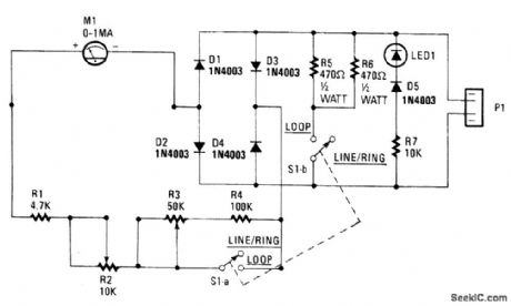
The telephone-line tester shown in the figure is connected to the telephone line through modular connector P1. Because the tester's LED polarity indicator is always connected when the tester is plugged in, the instant that the unit is connected, you will have an indication of the polarity. If it is correct-that is, if the green wire is the positive side and the red wire is the negative side-nothing will happen. If the situation is reversed, the LED will light.With switch S1 set for LINE/RING, both S1-a and S1-b are open and the meter indicates the con-dition of the line voltage. Any line-voltage reading in the LINE Ok range (more on the meter in a rno-ment) indicates a tine voltage that is higher than 40 Vdc. If the telephone is caused to ring, either by using a ringback number or by dialing from another phone, the meter will indicate RING Ok, and the LED will pulse (indicating ac), if the ringing voltage/current is correct. The actual position of the me-ter's pointer depends on how many ringers are connected across the line.When S1 is closed the voltage range of the meter is changed and a nominal load resistance of 230 Ω (R5 and R6) is connected across the line to emulate the off-hook load of the telephone. If the meter indicates LOOP Ok, you can be certain that you have sufficient loop voltage for satisfactory telephone operation. If you place another load on the line, perhaps by taking an extension telephone off hook, the meter reading will almost invariably drop below the LOOP Ok range. If lifting the hand-set causes the meter reading to drop;you can at least be certain that the telephone's hook switch is working and that the repeat coil is connected to the line. (View)
View full Circuit Diagram | Comments | Reading(0)
ION_DETECTOR
Published:2009/6/24 3:28:00 Author:May

ANT1 is a short whip antenna from a junked radio or other device. R3 is adjusted to bring the meter on scale. This device should be grounded to operate properly. A length of aluminum or copper foil tape attached to the instrument case makes contact with the hand, and the body senres as a ground via hand contact with this tape. (View)
View full Circuit Diagram | Comments | Reading(0)
OPTICAL_PROXIMITY_DETECTOR
Published:2009/6/24 3:25:00 Author:May
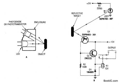
A reflector isolator (A) detects the presence of an object by bouncing light off of it. This tech-nique is useful in circuits that detect when an object is close enough to the sensor (B). (View)
View full Circuit Diagram | Comments | Reading(0)
ELECTRONIC_METRONOME
Published:2009/6/23 22:56:00 Author:May

RA sets the rate while R, sets the volume of clocks in the speaker. The 555 is configured as a low frequency oscillator. The circuit is powered 2N3904 by a 6 V battery. (View)
View full Circuit Diagram | Comments | Reading(0)
MOISTURE_DETECTOR
Published:2009/6/23 3:55:00 Author:May
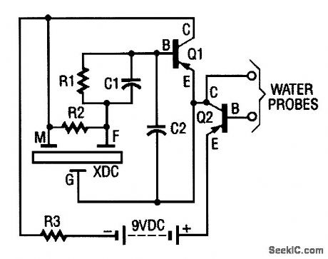

The moisture detector uses two transistors and a piezoelectric transducer to sound an alarm tone when water is present. Transistor Q1 forms a crystal-controlled oscillator, using a portion of piezoelectric transducer XDC-which contains two piezoelectric crystal regions-as the crystal. The transducer has three separate leads, One lead goes to each of the crystals, and the third lead is com-rnon to both.
The smaller internal crystal region sets the frequency of operation and the larger element is driven by Q1 (when it is biased on ) to provide the loud tone output. To turn the pnp transistor Q1 (used as an oscillator) on pnp transistor Q2 (used here as a switch) must be on. To turn it on with the biasing that is normally connected, you would only need to connect a resistor from the collector of Q2 to the base, which gives the base a negative (-) bias. The resistor used is the water that is to be detected. That turns Q2 on, which, in turn, turns on Q1. The result when water touches the probe is that the transducer emits a loud sound. (View)
View full Circuit Diagram | Comments | Reading(0)
SIMPLE_AUDIO_MIXER
Published:2009/6/23 3:45:00 Author:May

A single transistor is used as an audio mixer, the transistor serving as a feedback amplifier. (View)
View full Circuit Diagram | Comments | Reading(0)
ACID_RAIN_MONITOR
Published:2009/6/23 3:37:00 Author:May

The drain-to-source resistance of Q1 varies depending on the acidity of the sample presented to Q1's gate circuit. That variable resistance varies the current flowing through the bridge; that current is proportional to pH. (View)
View full Circuit Diagram | Comments | Reading(0)
BIRD_FEEDER_MONITOR
Published:2009/6/23 3:35:00 Author:May

The first amplifier circuit is a bird phone. In this circuit, the electret mike (MIC1) is mounted in the neck of a large plastic funnel. The amplifier, built around an MC34119 (which is available from D.C. Electronics, P.O. Box 3203, Scottsdale, AZ 85271-3203; Tel. 800-467-7736, and elsewhere), is then placed outside of the funnel with the pick-up facing a nearby bird feeder. The output of the amplifier is then connected to a 16-Ω speaker.
The amplifier's voltage gain is determined by the values of the input resistor (R1) and the feed-back resistor (R3 and R4, respectively). The differential gain of the amplifier is given by: R3 + R4/R1 × 2. With the component values shown, the maximum voltage gain is about 270. This permits listening to the activity at the bird feeder. (View)
View full Circuit Diagram | Comments | Reading(0)
| Pages:75/101 At 206162636465666768697071727374757677787980Under 20 |
Circuit Categories
power supply circuit
Amplifier Circuit
Basic Circuit
LED and Light Circuit
Sensor Circuit
Signal Processing
Electrical Equipment Circuit
Control Circuit
Remote Control Circuit
A/D-D/A Converter Circuit
Audio Circuit
Measuring and Test Circuit
Communication Circuit
Computer-Related Circuit
555 Circuit
Automotive Circuit
Repairing Circuit