
Measuring and Test Circuit
Index 66
20_kHz_RING_COUNTER
Published:2009/7/1 2:53:00 Author:May

The shift pulse turns off the conducting scs by reverse biasing the cathode gate.The charge stored on the coupling capacitor then triggers the next stage. An excessively long shift pulse charges up all the capacitors, turning off all stages. Grounding an anode gate will set that stage. (View)
View full Circuit Diagram | Comments | Reading(550)
RING_COUNTER_WITH_VARIABLE_TIMING
Published:2009/7/1 2:50:00 Author:May


Shift pulses are generated by the unijunction transistors. The intervals between pulses are controlled by CT and RT. A different RTcan be selected for each stage of the counter as shown.
(View)
View full Circuit Diagram | Comments | Reading(900)
DIGITAL_WRISTWATCH
Published:2009/7/1 2:48:00 Author:May

Single Intersil ICM7200 IC drives multiplexed display giving choice of hours and minutes, seconds, and day/date. CMOS chip divides 32.768-kHz crystal out-put in long internal binary divider to produce basic 1-s clock rate. Furtherdivision gives other elements of display. Pressing read button once gives hours and minutes;pressing second time gives day and date; and pressing third time gives seconds.-D. Lancaster, CMOS Cook-book, Howard W. Sams, Indianapolis, IN, 1977, p 377-378. (View)
View full Circuit Diagram | Comments | Reading(1942)
8_DIGIT_UP_DOWN_COUNTER
Published:2009/7/1 2:46:00 Author:May

This circuit shows how to cascade counters and retain correct leading zero blanking.The NAND gate etects whether a digit is active since one of the two segments a or bis active on any unblanked number. The flip flop is clocked by the least significant digit of the high order counter, and if this digit is not blanked, the Q output of the flip flop goes high and turns on the npn transistor, thereby inhibiting leading zero blanking on the low order counter. (View)
View full Circuit Diagram | Comments | Reading(1390)
METRONOME_Ⅱ
Published:2009/7/1 2:28:00 Author:May

This simple circuit uses a multivibrator to generate the beats and a subsequent audio amplifier stage to increase the output level. Range of adjustment is approximately from 40 to 200 beats per minute set by the gauged potentiometer. (View)
View full Circuit Diagram | Comments | Reading(608)
AUDIO_FREQUENCY_METER
Published:2009/7/1 2:27:00 Author:May

Circuit Notes
The meter uses time averaging to produce a direct current that is proportional to the frequency of the input signal. (View)
View full Circuit Diagram | Comments | Reading(0)
POWER_LINE_FREQUENCY_METER
Published:2009/7/1 2:26:00 Author:May

Circuit Notes
The meter will indicate the frequency from a power generator. Incoming sine waves are converted to square waves by the 100 K resistor and the 6.8 V zener. The square wave is differentiated by the capacitor and the current is averaged by the diodes. The average current is almost exactly proportional to the frequency and can be read directly on a 100 mA meter. To calibrate, hook the circuit up to a 60 Hz poweraline and adjust the 5 K pot to read 60 mA. (View)
View full Circuit Diagram | Comments | Reading(716)
LINEAR_FREQUENCY_METER(AUDIO_SPECTRUM)
Published:2009/7/1 2:24:00 Author:May

Circuit NotesThe 555 is used in a monostable multivibrator circuit that puts out a fixed timewidth pulse, which is triggered by the unknown input frequency. (View)
View full Circuit Diagram | Comments | Reading(650)
HEART_RATE_MONITOR
Published:2009/7/1 2:21:00 Author:May

Light filtering through the finger tip is detected by the cadmium sulphide photoresistor CD1 which forms the feedback network for transducer amplifier section ICA producing a weak signal which is further amplified by ICB. This signal is now compared against a user adjusted threshold, comparator ICD triggers gating on the piezoelectric buzzer PZ1. On each falligg edge of the comparator's output signal one-shot multivibrator ICD produces a 2 μs pulse which is inverted by Q1 and averaged by the RC network consisting of Ml, C6 and C7. The 10 K trimpot R20 in Q1's collector circuit sets the scale factor for M: where full scale is 150 beats per minute. (View)
View full Circuit Diagram | Comments | Reading(27)
GROUND_TESTER
Published:2009/7/1 2:18:00 Author:May

The circuit is simple and foolproof if wired correctly. Under normal conditions, only lamps 1 and 3 should be lit. If lamp 2 comes on, the cold lead is 117 volts above ground. (View)
View full Circuit Diagram | Comments | Reading(0)
DIODE_TESTING
Published:2009/7/1 2:14:00 Author:May

The circuit will display curves on a scope, contingent on the state of the diode. To calibrate, substitute a 1000-ohm resistor for the diode and adjust the scope gains for a 45-degree line. The drawings show some expected results. (View)
View full Circuit Diagram | Comments | Reading(713)
RESISTANCE_RATIO_DETECTOR
Published:2009/7/1 2:11:00 Author:May

Applications such as photoelectric control, temperature detection and moisture sensing require a circuit that can accurately detect a given resistance ratio. A simple technique that uses an op amp as a sensini element can provide 0.5% accuracy with low parts cost. The reed-relay contacts close when the resistance of the sensor Rp equals 47% of the standard Rs. Adjusting either R1 or R2 provides a variable threshold; the threshold is controlled by varying R3. For the most part, the type of resistors used for R1 and R2 determines the accuracy and stability of the circuit. With metal-ftlm resistors, less than 0.5% change in ratio sensing occurs over the commercial temperature range (0 to 70 C) with ac input variations from 105 to 135 V. (View)
View full Circuit Diagram | Comments | Reading(973)
INEXPENSIVE_FREQUENCY_COUNTER_TACHO_METER
Published:2009/7/1 2:02:00 Author:May

Circuit NotesThis circuit uses the low power ICM7555(CMOS 555)to generate the gating,STORE and RESET signals,To provide the gating stgnal,the timer IS configured as an astable multivibrator. The system is calibrated by using a 5 M potentiometer for Ra as a coarse control and a 1 jk potentiometer for Re as a fine control.CD40106B's are used as a monostable multivibrator and reset time delay. (View)
View full Circuit Diagram | Comments | Reading(691)
LOW_COST_FREQUENCY_INDICATOR
Published:2009/7/1 1:29:00 Author:May
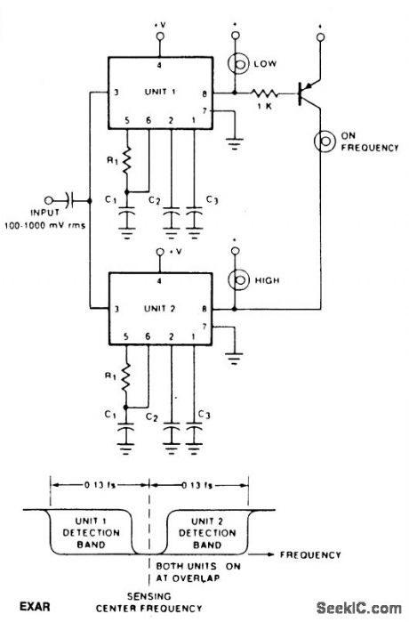
The circuit shows how two tone decoders set up with overlapping detection bands can be used for a go/no go frequency meter. Unit 1 is set 6% above the desired sensing frequency and Unit 2 is set 6% below the desired frequency.Now, if the incoming frequency is within 13% of the desired frequency, either Unit 1 or Unit 2 will give an output. If both units are on, it means that the incoming frequency is within 1% of the desired frequency. Three light bulbs and a transistor allow low cost read-out. The IC is an EXAR 567. (View)
View full Circuit Diagram | Comments | Reading(631)
POWER_FREQUENCY_METER
Published:2009/7/1 1:25:00 Author:May
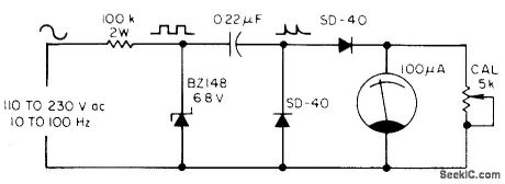
The meter uses a zener diode to form square waves from input she waves. After cal-ibration with the 5 k ohm potentiometer, the 100 μA meter reads directly in hertz. (View)
View full Circuit Diagram | Comments | Reading(1226)
PLANT_WATER_MONITOR
Published:2009/7/1 0:58:00 Author:May
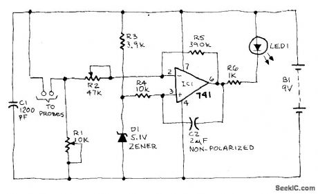
When the soil is moist, the LED glows. If the moisture falls below a certain predetermined level, the LED begins to flash. If there is still less moisture, the LED tums off. To calibrate, connect the battery and insert the probe into a container of dry soil. Set R1 to its maximum value then reduce that resistance until the LED begins to flash. The range over which the LED flashes before going out is adjusted using R2. (View)
View full Circuit Diagram | Comments | Reading(864)
ACID_RAIN_MONITOR
Published:2009/7/1 0:54:00 Author:May

A bridge rectifier and 12-volt regulator powers the MOSFET sensing circuit. The unregulated output of the bridge rectifier operates the drain solenoid via switch S1. The sensor itself is built from two electrodes, one made of copper, the other of lead. In combination with the liquid trapped by the sensor, they form a miniature lead-acid cell whose output is amplified by MOSFET Q1. The maximum output produced by our prototype cell was about 50μA. MOSFET Q1 serves as the fourth leg of a Wheatstone bridge. When acidity causes the sensor to generate a voltage, Q1 turns on slightly, so its drain-to-source resistanc decreases.That resistance variation causes an imbalance in the bridge, and that imbalance is indicated by meter M1.
(View)
View full Circuit Diagram | Comments | Reading(0)
ANGLE_OF_ROTATION_DETECTOR
Published:2009/7/1 0:45:00 Author:May

The figure shows two TL3103 linear Hall-effect devices used for detecting the angle of rotation. The TL3103s are centered in the gap of a U-shaped permanent magnet. The angle that the south pole makes with the chip face of unit #1 is defined as angle 0. Angle 0 is set to 0° when the chip face of unit #1 is perpendicular to the south pole of the magnet. As the south pole of the magnet sweeps through a 0° to 90°angle, the output of the sensor increases from 0°. Sensor unit #2 decreases from its peak value of +Vp at 0° to a value VOQ at 90°. So, the output of sensor unit #1 is a sine function of 0 and the output of unit #2 is a cosine function of 0 as shown. Thus, the first sensor yields the angle of rotation and the second sensor indicates the quadrant location. (View)
View full Circuit Diagram | Comments | Reading(1328)
TOXIC_GAS_DETECTOR
Published:2009/7/1 0:41:00 Author:May
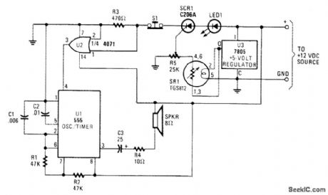
The major device in the circuit is SR1(a TGS812 toxic-gas sensor manufactured by Figaro Engineering Inc.) The gas-sensitive semiconductor (acting like a variable resistor in the resence of toxic gas) decreases in electrical resistance when gaseous toxins are absorved from the sensor surface. A 25,000 ohm potentiometer(R5) connected to thesensor serves as a load, voltage-dividing network, attd sensitivity control and has itscenter tap connected to the gate of SCR1,When toxic fumes come h contact with thesensor,decreasing its electrical resistance,current flows through the load (potentiometer R5).The voltage developed across the wiper of R5,which is connected to the gate of SCR1,triggers the SCR into conduction。With SCR1 now conducting,pin 1-volt Supplyfor the semiconductor elements of the TGS812 h1 spite of the suggested 10 volts,thusreducing the standby current.A 7805 regulator IS used to meet the 5-volt requlrementfor the heater and semiconductor elements. (View)
View full Circuit Diagram | Comments | Reading(5217)
GAS_AND_VAPOR_DETECTOR
Published:2009/7/1 0:34:00 Author:May
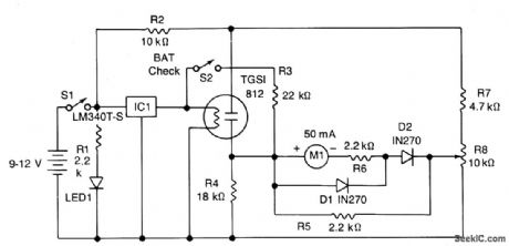
The power drain is approximately 150 mA. IC1 provides a regulated 5-volt supply for the filament heater of the sensor. The gas sensitive element is connected as one arm of a resistance bridge consisting of R4, R7, R8 and the meter Ml with its associated resistors R5 and R6. The bridge can be balanced by adjusting R8 so that no current flows through the meter. A change in the sensor's resistance, caused by detection of noxious gases, will unbalance the circuit and deflect the meter. Diodes D1, D2 and resistor R5 protect the meter from overload while R6 determines overall sensitivity. R2 limits the current through the sensor; R1 and LED1 indicate that the circuit is working, so that you do not drain the battery leaving the unit on inadvertently; R3 and S2 give a battery level check. (View)
View full Circuit Diagram | Comments | Reading(631)
| Pages:66/101 At 206162636465666768697071727374757677787980Under 20 |
Circuit Categories
power supply circuit
Amplifier Circuit
Basic Circuit
LED and Light Circuit
Sensor Circuit
Signal Processing
Electrical Equipment Circuit
Control Circuit
Remote Control Circuit
A/D-D/A Converter Circuit
Audio Circuit
Measuring and Test Circuit
Communication Circuit
Computer-Related Circuit
555 Circuit
Automotive Circuit
Repairing Circuit