
Measuring and Test Circuit
Index 74
PRECISION_PHOTODIODE_LEVEL_DETECTOR
Published:2009/6/24 23:49:00 Author:May
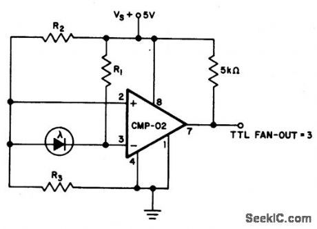
For R1=2.5 M,R2=R3=5 M.The output state changes at a photo diode current of 0.5μA (View)
View full Circuit Diagram | Comments | Reading(588)
LIGHT_INTERRUPTION_DETECTOR
Published:2009/6/24 23:44:00 Author:May
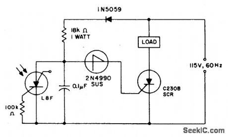
When the light incident on the LASCR is interrupted, the voltage at the anode to the 2N4990 unilateral switch goes positive on the next positive cycle of the power which in turn triggers the switch and the C230 SCR when the switching voltage of the unilateral switch is reached. This will cause the load to be energized for as long as light is not incident on the LASCR. (View)
View full Circuit Diagram | Comments | Reading(1465)
ENLARGER_EXPOSURE_METER
Published:2009/6/24 23:36:00 Author:May

Two gates of a 4011 are used as a comparator. When the resistance of R4 decreases the voltage at pin 1 and 2 increases, producing a logic zero at pin 3, causing pin 4 to go high and activating the LED. R3 is calibrated in light units, or seconds exposure time. To calibrate, set pot R3 so as to just be on the LED ON/OFF threshold. With a light level that is suitable to correctly expose a photographic print, use a known enlarger and a known negative. (View)
View full Circuit Diagram | Comments | Reading(0)
PTOXIMITY_DETECTOR
Published:2009/6/24 23:09:00 Author:May

The proximity sensor works on the principle of transmitting a beam of modulated infra-red light from the emitter diode LED2, and receiving reflections from objects passing in front of the beam with a photodiode detector D1. The circuit can be split into three distinct stages; the infra-red transmitter, the photodiode amplofoer, and a variable threshol comparator. (View)
View full Circuit Diagram | Comments | Reading(0)
TOUCH_SWOTCH_OR_PROXIMITY_DETECTOR
Published:2009/6/24 23:04:00 Author:May

This circuit is actuated by an increase in capacitance between a sensing electrode and the ground side of the line. The sensitivity can be adjusted to switch when a human body is within inches of the insulated plate used as the sensing electrode. Thus, sensitivity is adjusted with the 1 megohm potentiometer which de-termines the anode voltage level prior to clamping. This sensitivity will be proportional to the area of the surface opposing each other. (View)
View full Circuit Diagram | Comments | Reading(0)
ENLARGING_LIGHT_METER
Published:2009/6/24 22:52:00 Author:May

Meter M1, a +/-50-μA zero-center D'Arsonval meter movement is driven by U1, a TL081 FET op amp, through R3. The gain of UI is set at 11 by R1 and R2, while capacitor C1 is used to restrict the bandwidth of U1 to 1.6 Hz. Power for the circuit is derived from a simple dual-polarity 12-V power supply (consisting of T1, D3, D4, C2, and C3).
A light-dependent resistor (LDR), R16 (which is a semiconductor element whose resistance decreases as it is exposed to increasing illumination), is used as a light-sensing device. One end of R16 is connected to the negative supply rail through R12, and the other end is connected to pin 3 of U1, applying a negative current to U1. A variable (over a 4:1 range) positive current determined by the settings of R14 and S1 (and derived from the positive supply rail) is also fed to pin 3 of U1.
When the two currents (of opposite polarities) are equal, they cancel each other out, so effectively no current is applied to pin 3 of U1. With no current applied to pin 3, the output of U1 is zero and meter M1 registers accordingly, indicating a null. However, when light striking R16 causes its re-sistance to decrease, the current through the device increases, making the negative current greater than the positive current. Under that condition, the negative current causes the output of U1 to swing negative, causing the pointer to swing in the negative direction.
That indicates that the light intensity must be reduced by using a smaller lens opening on the en-larger (smaller f/stop). The opposite occurs if the light is too dim. Lamp 11, a 12-V 60-mA grain of wheat unit, is used to illuminate the meter scale, and R15 is used to limit the meter's illumination to a faint glow that is just bright enough so that the face of M1 can be plainly seen in a photo darkroom. Resistors R3 and R4 should be selected for the meter used. With a dual supply of +/-12 V, U1 produces an output voltage of 10 V peak-to-peak. The resistance of R3 can be found by dividing the peak voltage (i.e., 10/2) by the full-scale meter current (in amps); i.e., R3 = (10/2)/0.0005 = 100,000 Ω. R4, the shunt resistor, should be selected to have a value equal to the meter's internal resistance. (View)
View full Circuit Diagram | Comments | Reading(1420)
10_GHz_WAVEGUIDE_DETECTOR_FOR_AMATEUR_RADIO_USE
Published:2009/6/24 22:31:00 Author:May
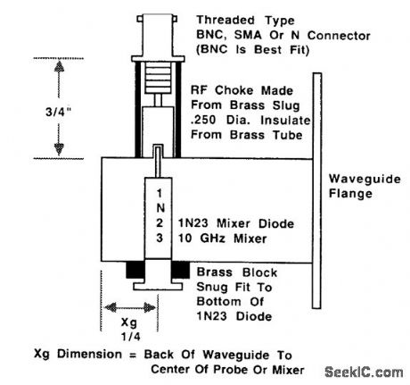
This shows the construction of a waveguide detector for use at the 10-GHz amateur radio fre-quencies. (View)
View full Circuit Diagram | Comments | Reading(849)
LOW_VOLTAGE_MONITOR
Published:2009/6/24 22:29:00 Author:May
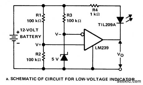
This circuit monitors the voltage of a battery and warns the operator when the battery voltage is below a preset level by turning on an LED. The values are set for a 12V automobile battery. The preset value is 10 volts. (View)
View full Circuit Diagram | Comments | Reading(799)
DOUBLE_ENDED_VOLTAGE_MONITOR
Published:2009/6/24 22:12:00 Author:May
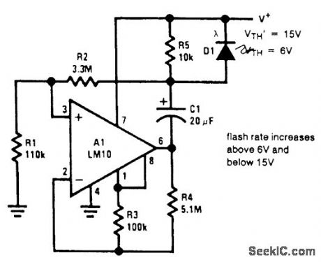
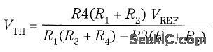
This circuit has the added feature that it can sense an over-voltage condition. The lower activa-Lion threshold is given by equation (1), but above a threshold, oscillation again ceases. Below VTH, the op amp output is saturated negative, but above VTH, it is saturated positive. The flash rate approaches zero near either limit. (View)
View full Circuit Diagram | Comments | Reading(0)
INEXPENSIVE_VOLTAGE_CALIBRATOR
Published:2009/6/24 22:10:00 Author:May
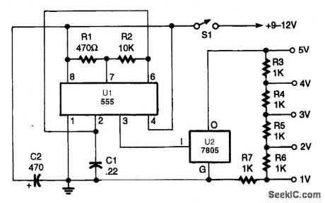
In the voltage calibrator, two low-cost ICs-a 555 oscillator/timer and a 78055 5-V 1.5-A voltage regulator-along with a precision voltage divider network are used to provide outputs of 1- to 5-V peak-to-peak. (View)
View full Circuit Diagram | Comments | Reading(1386)
EXPANDED_SCALE_dc_METER_FOR_12_V_SYSTEMS
Published:2009/6/24 22:08:00 Author:May
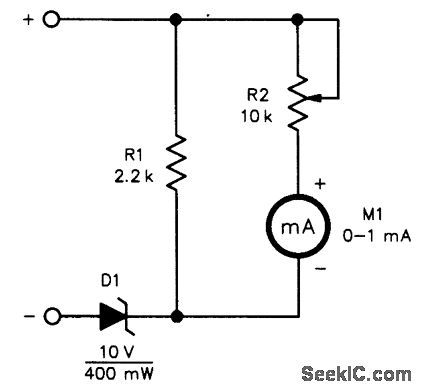


This circuit can be used to monitor a 12-V system with a meter reading10 V to another volt-age. Expect 10 to 20 V, depending on the setting of R2. Depending on the characteristics of D1, R1 might be increased or eliminated entirely. (View)
View full Circuit Diagram | Comments | Reading(561)
dc_VOLTMETER
Published:2009/6/24 22:08:00 Author:May
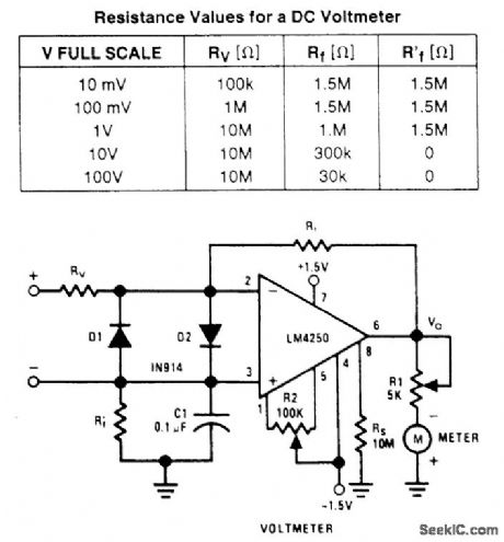
A wide-range voltmeter circuit. This inverting amplifier has a gain varying from -30 for the 10-mV full-scale range to -0.003 for the 100-V full-scale range. Diodes D1 and D2 provide com-plete amplifier protection for input overvoltages as high as 500V on the 10-mV range, but if over-voltages of this magnitude are expected under continuous operation, the power rating of RV should be adjusted accordingly (View)
View full Circuit Diagram | Comments | Reading(2551)
VOLTAGE_MONITOR
Published:2009/6/24 22:04:00 Author:May
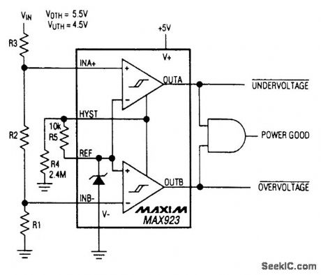
A MAX923 dual comparator is used as a window detector, For a threshold of 4.5V and 5.5V, R1=1.068MΩ, R2=61.9kΩ and R3=1MΩ (View)
View full Circuit Diagram | Comments | Reading(0)
AUTO_LIGHTS_ON_REMINDER
Published:2009/6/24 21:58:00 Author:May

The alarm is composed of a diode, buzzer, and limiting resistor. The diode serves as a switch which allows the buzzer to sound off only when the light switch is closed and the ignition is turned off. (View)
View full Circuit Diagram | Comments | Reading(584)
CAR_BATTERY_CONDITION_CHECKER
Published:2009/6/24 21:55:00 Author:May
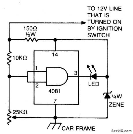
This circuit uses an LED and 4081 CMOS integrated circuit. The variable resistor sets the voltage at which the LED turns on. Set the control so that the LED lights when the voltage from the car's ignition switch drops below 13.8 volts. The LED normally will light every now and then for a short period of time. But, if it stays on for very long, your electrical system is in trouble. (View)
View full Circuit Diagram | Comments | Reading(1053)
WINDSHIELD_WASHER_FLUID_WATCHER
Published:2009/6/24 21:54:00 Author:May
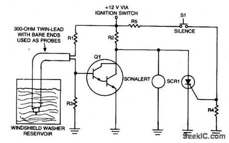
This circuit relies upon the minute current between two conductive probes sus-pended in a washer fluid reservoir. When the level is below the probes, Q1 turns on and the Sonolert sounds. (View)
View full Circuit Diagram | Comments | Reading(567)
CAR_BATTERY_MONITOR
Published:2009/6/24 21:52:00 Author:May

Waring light (LED) indicates when battery Voltage falls below level set by 10 K pot. Can indicate that battery is defective or needs charging if cranking drops battery vlotage belpw preset safe limit. (View)
View full Circuit Diagram | Comments | Reading(834)
VIDEO_IF_AMPLIFIER_DETECTOR
Published:2009/6/24 21:44:00 Author:May

View full Circuit Diagram | Comments | Reading(0)
ONE_OF_TWO_VIDEO_SELECTOR
Published:2009/6/24 21:41:00 Author:May

View full Circuit Diagram | Comments | Reading(498)
PROXIMITY_DETECTOR
Published:2009/6/24 21:41:00 Author:May

This circuit provides a means of detecting the presence of anything by the reflection of infra-red light and provides a direct digital output of object detection. By the use of modulation and high power bursts of infra-red at a very low duty cycle, a detection range of over a foot is achieved. Works on the principle of transmitting a beam of modulated infra-red light from the emitter diode LED2, and receiving reflections from objects passing in front of the beam with a photodiode detector D1. The circuit consists o f an infra-red transmitter, photodiode amplifier, and a variable threshold comparator. (View)
View full Circuit Diagram | Comments | Reading(2328)
| Pages:74/101 At 206162636465666768697071727374757677787980Under 20 |
Circuit Categories
power supply circuit
Amplifier Circuit
Basic Circuit
LED and Light Circuit
Sensor Circuit
Signal Processing
Electrical Equipment Circuit
Control Circuit
Remote Control Circuit
A/D-D/A Converter Circuit
Audio Circuit
Measuring and Test Circuit
Communication Circuit
Computer-Related Circuit
555 Circuit
Automotive Circuit
Repairing Circuit