
Measuring and Test Circuit
Index 79
FURNACE_FUEL_MISER_2
Published:2009/6/19 3:45:00 Author:May
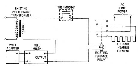
Electric-heating systems may or may not use a relay in the thermostat c ircuit. Those that do have a relay can be controlled by the Fuel Miser by wiring its output circuit in series with the relav coil connections as shown here. (View)
View full Circuit Diagram | Comments | Reading(581)
FURNACE_FUEL_MISER_1
Published:2009/6/19 3:43:00 Author:May
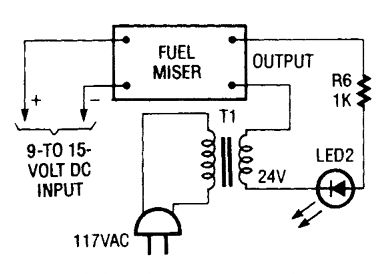
When the circuit is working properly the output circuitry can be checked using a 24-volt step-down transformer, a lk resistor, and an LED. Together those components simulate the load that the Fuel Miser sees during normal operation. (View)
View full Circuit Diagram | Comments | Reading(611)
NANOAMMETER
Published:2009/6/19 3:42:00 Author:May

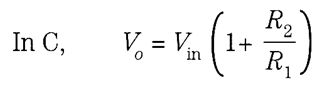
Potentiometer R2 provides an electrical meter zero by forcing input offset voltage Vos, to zero. Full-scale meter deflection is set by R1. Both RI and R2 only need to be set once for each op amp and meter combination. For a 50-μA 2-kΩ meter movement, R1 should be about 4kΩ to give full-scale meter deflection in response to a 300-mV output voltage. Diodes Dl and D2 provide full input pro-tection for overcurrents up to 75 mA.With an R, resistor value of 1.5 MΩ, the circuit becomes a nanoammeter with a full-scale reading capability of 100 nA. Reducing Rf, to 3 kΩ in steps, as shown in the figure increases the full-scale de-flection to 100μA, the maximum for this circuit configuration. The voltage drop across the two input terminals is equal to the output voltage(Vo)divided by the open loop gatn. Assume that an open loop gain of 10,000 gives an input voltage drop of 30μV or less. (View)
View full Circuit Diagram | Comments | Reading(2)
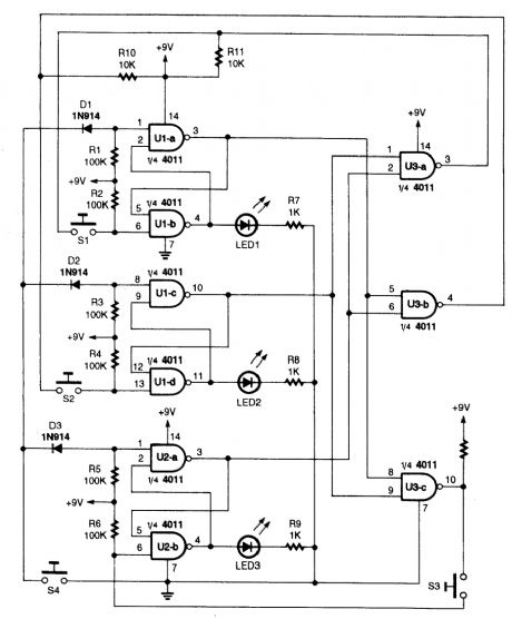
THREE_NPUT_FIRST_RESPONSE_MONITOR
Published:2009/6/19 3:39:00 Author:May
View full Circuit Diagram | Comments | Reading(737)
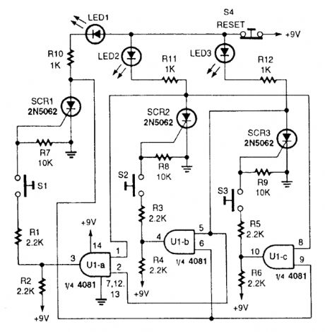
FIRST_RESPONSE_MONITOR_I
Published:2009/6/19 3:33:00 Author:May
Three interlocked flip-flops enable the detection of the first input. S1, S2, and S3 are inputs.Analog switches controlled by logic gates, or other logic circuitry could be sub-statement for S1, S2, and S3. (View)
View full Circuit Diagram | Comments | Reading(592)
NOVEL_RF_POWER_METER
Published:2009/6/19 3:32:00 Author:May
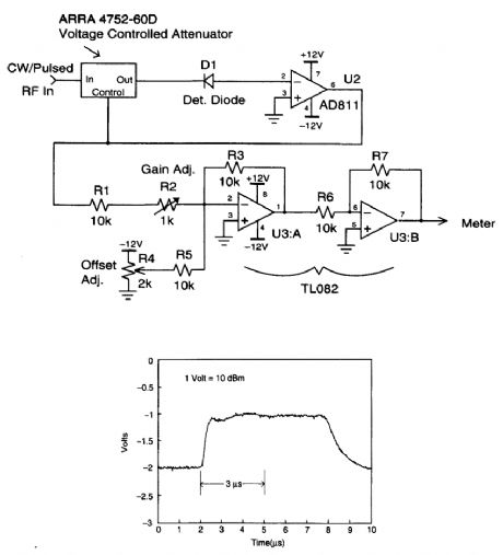
The circuit matches the diode with a voltage-variable attenuator that has a logarithmic response. By varying the attenuation until the diode output is zero, the resulting attenuation value then corre-sponds to the input power level. Because the voltage-variable attenuator's output is logarithmic, diode nonlinearities become negligible. (View)
View full Circuit Diagram | Comments | Reading(656)
TWO_REMOTE_METERS
Published:2009/6/19 3:29:00 Author:May
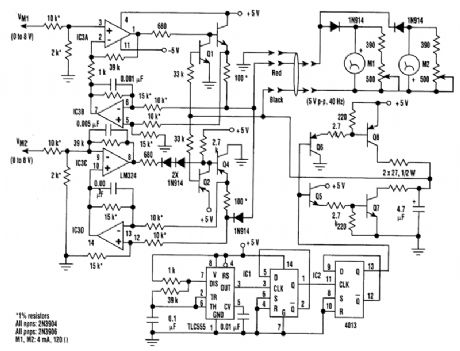
Two remote meters can be driven independently using just one wire pair. This“constant current”design eliminates the effects of wire-pair resistance up to 200Ω. Driving two remote meters inde-pendently usually requires two wire pairs(one pair for each meter).In the circuit, IC1 and IC2 generate a 40-Hz symmetrical square wave (the frequency isn't criti-cal). Q5 through Q8 amplify tl)e square wave to 5 Vp-p, which is applied to the return (black wire)for the remote meters.Amplifier IC3A buffers the input signal voltage Vmi, intended for meter M1(0 to 8V), and sends it through emitter-follower Q3 to a 100-Q current-sense resistor. The other end of this resistor is tied to the supply (red wire) of the remote meters. IC3B amplifies the voltage across the sense resistor, which corresponds to the current sent to remote meter MI, and closes the feedback loop to IC3A.This results in a voltage of 0 to 8V at the Ml input, generating a current of 0 to 10 mA to M1.Transistor Q1 gates this current on and off synchronous to the 40-Hz square wave so that meter MI actually sees a 50% 0-to-+10-mA peak(0 to 5 mA average)current.Similarly, IC3C, IC3D, Q2, and Q4 provide a 0- to -10-mA peak current for M2. Ml and M2 are isolated by the two-reverse-conn ected 1N914 diodes in the remote-meter box. Variable resistors across Ml and M2 permit calibration. The extra 1N914 diode in the M2 drive circuit prevents inter-ference between MI and M2. (View)
View full Circuit Diagram | Comments | Reading(515)
OPTICAL_ISOLATOR_WATTMETER
Published:2009/6/19 2:45:00 Author:May
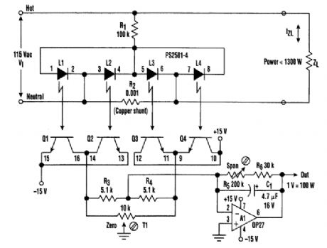
The quad-channel optical isolator, consisting of LED L1 through L4 and phototransistors Q1 through Q4, is connected in a double bridge configuration. The arrangement serves to compute the four-quadrant product of ac line voltage and 21 load current. The result is an accurate representa-tion of the true instantaneous power delivered to the load--even if the line voltage wanders and the load is reactive and nonlinear. This wattmeter function is, of course, optically isolated from the ac line, has full-scale limit of 1300 W, and is output with scale factor of 1 V/100 W. (View)
View full Circuit Diagram | Comments | Reading(2312)
ANALOG_TACHOMETER_CIRCUIT
Published:2009/6/19 2:41:00 Author:May

In this tachometer circuit a 555 is used as a pulse shaper. The dc value of the integrated pulse train is read by M1 which is calibrated to read frequency. With the values shown, the meter will read 0-1 kHz. (View)
View full Circuit Diagram | Comments | Reading(5690)
ANALOG_TACHOMETER_CIRCUITS
Published:2009/6/19 2:41:00 Author:May
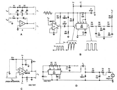
The four circuits shown are: a passive and active integrator, an analog tachometer, a scaling amplifier, and a capacitance meter. (View)
View full Circuit Diagram | Comments | Reading(1095)
MOTORCYOLE_HEADLIGHT_MONITOR
Published:2009/6/19 2:37:00 Author:May

The headlight on most newer bikes is keyed on with the ignition switch to guarantee that you are never underway without your headlight be-ing on. However, many older bikes have a fac-tory headlight switch, and a growing number of the newer bikes are owner-modified in the same way.A simple headlight monitor circuit consists of just an LED and a current-limiting resistor wired across the headlight switch, as shown.When the ignition is on and the headlight switch is off, the LED will glow. (View)
View full Circuit Diagram | Comments | Reading(520)
ELECTROSCOPE
Published:2009/6/19 2:32:00 Author:May
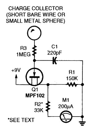
This circuit is useful for detecting electrostatic charges. In operation, C1 reduces ac noise, but lowers the sensitivity a bit. The MPF102 and R1 form a voltage divider. When the FET's gate is earth-grounded, the divider's output will be about 4.5 V giving a half-scale reading on Ml, a 200-μA meter. A positively charged object(like cotton-rubbed glass)will give a positive deflection from half-scale, and a negatively charged object (a plastic comb, for ex-ample)will give a negative meter deflection.The whole circuit(including the 9-V battery supply)should be in a metal enclosure, and a short piece of bare wire makes a fine charge collector. (View)
View full Circuit Diagram | Comments | Reading(3)
AUTO_RANGING_DIGITAL_CAPACITANCE_METER
Published:2009/6/19 2:23:00 Author:May

This digital capacitance meter reads from 1 pF to 1000 μF. Basically, a timer(U4)uses the unknown capacitance to generate a pulse of duration, depending on the value of unknown capacitance, and the pulse duration is measured. The display is an LCD 0003 driven by a 74C947 counter/display driver. (View)
View full Circuit Diagram | Comments | Reading(1499)
CAR_ALTERNATOR_MONITOR_IDIOT_LIGHT
Published:2009/6/19 2:17:00 Author:May
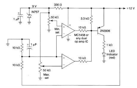
A window comparator is used to detect a too-low or a too-high system voltage. The minimum and maxirnum settings are set with two 50-kΩ pots, as desired. (View)
View full Circuit Diagram | Comments | Reading(1962)
DIGITAL_BAROMETER
Published:2009/6/19 2:02:00 Author:May
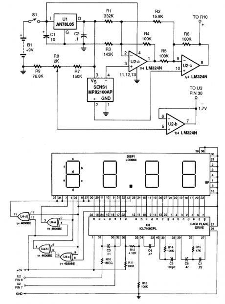


A pressure sensor is used in this application. This outputs a voltage to amplifier U2, and a 3 1/2 digit A/D converter module. It is calibrated to read barometric pressure in inches of mercury. (View)
View full Circuit Diagram | Comments | Reading(859)
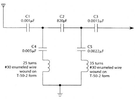
AM_BROADCAST_TRAP_FOR_SIMPLE_SW_RECEIVERS
Published:2009/6/19 2:00:00 Author:May
View full Circuit Diagram | Comments | Reading(609)
STEREO_BALANCE_METER
Published:2009/6/19 1:54:00 Author:May

When L & R signals are equal, no output is present frorrt U1, and pin 6 is at a steady 4.5 V. Un-balanced audio causes the LEDs to vary in brightness, which causes a difference that corresponds to unbalance between channels. (View)
View full Circuit Diagram | Comments | Reading(0)
ELF_MONITOR
Published:2009/6/19 1:42:00 Author:May

A telephone pick-up coil is used as a sensor for low-frequency magnetic fields. The signal is amplified and detected, then used to drive a comparator. (View)
View full Circuit Diagram | Comments | Reading(2293)
AUDIO_FREQUENCΥ_METER
Published:2009/6/18 23:58:00 Author:May

A pulse-shaper is used in a tachometer cir-cuit to drive a meter. (View)
View full Circuit Diagram | Comments | Reading(631)
FOUR_WIRE_RESISTANCE_MEASUREMENT_HOOkUP
Published:2009/6/18 23:57:00 Author:May
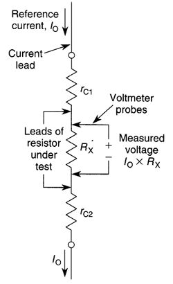
A true four-wire resistance measurement hookup. (View)
View full Circuit Diagram | Comments | Reading(619)
| Pages:79/101 At 206162636465666768697071727374757677787980Under 20 |
Circuit Categories
power supply circuit
Amplifier Circuit
Basic Circuit
LED and Light Circuit
Sensor Circuit
Signal Processing
Electrical Equipment Circuit
Control Circuit
Remote Control Circuit
A/D-D/A Converter Circuit
Audio Circuit
Measuring and Test Circuit
Communication Circuit
Computer-Related Circuit
555 Circuit
Automotive Circuit
Repairing Circuit