Measuring and Test Circuit
TWO_REMOTE_METERS
Published:2009/6/19 3:29:00 Author:May | From:SeekIC

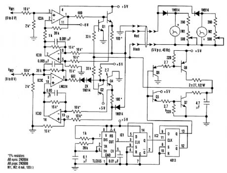
Two remote meters can be driven independently using just one wire pair. This“constant current”design eliminates the effects of wire-pair resistance up to 200Ω. Driving two remote meters inde-pendently usually requires two wire pairs(one pair for each meter).In the circuit, IC1 and IC2 generate a 40-Hz symmetrical square wave (the frequency isn't criti-cal). Q5 through Q8 amplify tl)e square wave to 5 Vp-p, which is applied to the return (black wire)for the remote meters.Amplifier IC3A buffers the input signal voltage Vmi, intended for meter M1(0 to 8V), and sends it through emitter-follower Q3 to a 100-Q current-sense resistor. The other end of this resistor is tied to the supply (red wire) of the remote meters. IC3B amplifies the voltage across the sense resistor, which corresponds to the current sent to remote meter MI, and closes the feedback loop to IC3A.This results in a voltage of 0 to 8V at the Ml input, generating a current of 0 to 10 mA to M1.Transistor Q1 gates this current on and off synchronous to the 40-Hz square wave so that meter MI actually sees a 50% 0-to-+10-mA peak(0 to 5 mA average)current.Similarly, IC3C, IC3D, Q2, and Q4 provide a 0- to -10-mA peak current for M2. Ml and M2 are isolated by the two-reverse-conn ected 1N914 diodes in the remote-meter box. Variable resistors across Ml and M2 permit calibration. The extra 1N914 diode in the M2 drive circuit prevents inter-ference between MI and M2.
Reprinted Url Of This Article:
http://www.seekic.com/circuit_diagram/Measuring_and_Test_Circuit/TWO_REMOTE_METERS.html
Print this Page | Comments | Reading(3)

Article Categories
power supply circuit
Amplifier Circuit
Basic Circuit
LED and Light Circuit
Sensor Circuit
Signal Processing
Electrical Equipment Circuit
Control Circuit
Remote Control Circuit
A/D-D/A Converter Circuit
Audio Circuit
Measuring and Test Circuit
Communication Circuit
Computer-Related Circuit
555 Circuit
Automotive Circuit
Repairing Circuit
Code: