
Measuring and Test Circuit
Index 69
SEQUENTIAL_TIMER
Published:2009/6/29 2:07:00 Author:May

Many applications, such as computers, re-quire signals for initializing conditions during start-up. Other applications such as test equipment require activation of test signals in sequence. SE555/NE555 circuits may be connected to provide such sequential control. The timers may be used in various combinations of astable or monostable circuit connections, with or without modulation, for extremely flexible waveform control. (View)
View full Circuit Diagram | Comments | Reading(355)
THUMBWHEEL_PROGRAMMABLE_INTERVAL_TIMER
Published:2009/6/29 2:06:00 Author:May

Switch programmable on/off or interval timer, has three relay-switched outputs. 0ut-put one is active for the duration of time 1, output two is active for the duration of time 2, and output three is active for the duration of both one and two. Timing data is input through 6 BCD-encoded thumbwheel switches. Three SPST switches inform the WD-55 to interpret this data as NNN seconds. NNN seconds, NNN minutes, or NNN hours. The LED display will show the time remaining and the countdown when operating. Since the data is input through switches, the display may be deleted. Also, since the timing information is read from switches, the data is nonvolatile and no battery backup is required. (View)
View full Circuit Diagram | Comments | Reading(1239)
MEIER_THERMOMETER_WITH_TRIMMED_OUTPUT
Published:2009/6/29 1:49:00 Author:May

View full Circuit Diagram | Comments | Reading(552)
OPTICAL_PYROMETER
Published:2009/6/29 1:41:00 Author:May

View full Circuit Diagram | Comments | Reading(870)
2_W_MONITOR
Published:2009/6/29 1:37:00 Author:May

Fairdlild 759 opamp provides 1-W AF output when supply is ±9V and loudspeaker is 16 ohms,and 2 W with ±15V and 32ohm loudspeaker. Use heatsink,Gain is 20 for values shown with response rolled off at 15 kHz by C1,-W Jung,An10 Op Amp Update,Ham Radio,March 1978、p 62-69 (View)
View full Circuit Diagram | Comments | Reading(712)
Simple illumination photometry instrument circuit diagram
Published:2011/7/28 4:44:00 Author:Sophia | Keyword: Simple illumination photometry instrument

When the outside light is dark, the photodiode BG1 shows large resistance and allows small current. So, BG2 ends, BG2 connects, LED1 lights.
When the light is bright, BG1 outputs strong current, so that BG2 can be in the saturation, BG3 ends and BG4 connects, LED1 is off and LED2 (red) lights.
When the light is normal, three transistors are in amplified state. two LEDs emit dim light.
(View)
View full Circuit Diagram | Comments | Reading(635)
TIMER_FOR_WIPER
Published:2009/6/28 23:49:00 Author:May

Provides automatic one-shot swipes at preselected intervals from 2 to 30 s for handling mist, drizzle, or splash from wet road. Circuit shorts out homing switch inside windshield-wiper mptor, which is usually in parallen with slow-speed contacts of wiper dashboard switch terminals at a time to find pins that shatr wiper. When blades begin moving, remove jumper; blades should then finish sweep and shut off. It is these terminals of switch that are connected to points A and B of control circuit.-V. Mele, Mist Switch-It's for Your Windshield Wipers, Popular Science, Aug.1973, p 110. (View)
View full Circuit Diagram | Comments | Reading(629)
The light detecion 4-20mA current transformer circuit
Published:2011/7/21 2:56:00 Author:Seven | Keyword: light detecion, current transformer

Figure 2-141. The light detecion 4-20mA current transformer circuit (View)
View full Circuit Diagram | Comments | Reading(1893)
REGULATOR_FOR_ALTERNATOR
Published:2009/6/28 23:09:00 Author:May

Simple and effective solid-state replaeement for auto voltage regulator can be used with altemator in almost any negative-ground system. Circuit acts as switch supplying either full or no voltage to field winding of altemator. When battery is below 13 V, zenel D1 does not conduct, Q1 is off, Q2 is on, and full battery voltage is applied to alternator field so it puts out full voltage to battery forcharging. When battery reaches 13.6 V, Q1 tums on, Q2 tums off, altemator output is reduced to zero, and battery gets no charging current. Corcuit can also be used with wind-drivent alternator systems.-P.S.Smith, $22 for a Regulator? Never!, 73 Magazine, Holifay issue 1976, p 103. (View)
View full Circuit Diagram | Comments | Reading(3954)
DUAL_RANGE_RF_WATTMETER
Published:2009/6/28 23:07:00 Author:May

Uses circuit which is not frequency-sensitive, so calibration can be accurate over wide frequency spectrum, Ranges are 0-1 and 0-10 W. L2 is 7-50-2 toroid wound almost full with No. 28 enamel, leaving only room for 2-tum link L1.C1 and C2 are 3-20 pF trimmers. Article covers calibiation and use and gives table for reading SWR by comparing watts FORWARD with watts REFLECTED,-A,Weiss、The Silk-Purse In-Line Wattmeter、CQ,May 1977 p 50-52 and 74-75 (View)
View full Circuit Diagram | Comments | Reading(1260)
FIELD_STRENGTH_METER_2
Published:2009/6/28 23:07:00 Author:May

Developed for tuning all types of antennas, from mobile whips to four-element quads. Avoids shielding and other problems of switched T pads for calibrated attenuator by first detecting RF, then attenuating DC output. Technique has added advantage that circuit is no longer frequency-sensitive. To cover 13-24 MHz, L2 is 11 tums spaced out to about 1 inch, with 2 turns overtop for L1. D1 can be any diode such as 1N34. R1 serves as calibrated attenuator, with R2 in series giving 0-dB point at junction. Article covers construction and operation.-J. L. liffe, An Amplified, Cali-brated, Signal Strength Meter, 73 Magazine, June 1973, p 85-86. (View)
View full Circuit Diagram | Comments | Reading(1114)
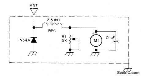
TUNED_RADIATED_FIELD_METER
Published:2009/6/28 23:06:00 Author:May

Provides quick check of transmitter performance and approximate check offrequency,Valuesfor L1 and C1 are chosen to cover desired frequency range,Metercan be 1 mA or 200μA,Keep lead lengthsshort-E.Hartz Is My Rig Working or Not?、73Magazine. Oct 1976、p 56-57 (View)
View full Circuit Diagram | Comments | Reading(605)
FIELD_STRENGTH_METER_1
Published:2009/6/28 23:05:00 Author:May

Easily assembled for checking performance of amateur radio transmitter and its antenna system.-Circuits, 73 Magazine, Jan. 1974, p 128. (View)
View full Circuit Diagram | Comments | Reading(520)
DIGITAL_TACHOMETER
Published:2009/6/28 23:05:00 Author:May

Pulses from auto engine points or other pickoff are filtered before feed to 3130 CMOS opamp used as comparator to complete conditioning of input. Pulses are then fed through 4046 PLL to divide-by-N counter that is set for number of cylinders in engine (60 for four cylinders, 45 for six, and 30 for eight). Output frequency is then counted for 0.5 s to get engine or shah speed in rpm.-D. Lancaster, CMOS Cookbook, Howard W. Sams, Indianapolis, IN, 1977, p 36-367. (View)
View full Circuit Diagram | Comments | Reading(2601)
SWR_METER
Published:2009/6/28 23:03:00 Author:May

Gives direct measurement of standingwave ratio on transmission line, independent of absolute power levels and of frequency. Voltages of 1N4002 silicon diodes are proportional to logarithms of their cuffents, which in tum are proportional to forward and reflected voltages. Meter scale is nonlinear, with maximum sensitivity as SWR approaches 1:1. For 50-ohm Iine, use 220 for R2 and 27 for R3 and R4. For 75-ohm line, corresponding values are 180 and 33. Detector diodes are pointcontact germanium rated at 80 PIV. Articlegives construction details and calibration curve. Ferrite ring is Mullard FX1596 or equivalent, with 0.5-inch outside diameter. Ground coax braid at one end only.-P. G. Martin, Some Directional Wattmeters and a Novel SWR Meter, 73 Mag-azine, Aug. 1974, p 17, 19-21, 23-24, and 26. (View)
View full Circuit Diagram | Comments | Reading(7588)
DIRECTlONAL_WATrMETER
Published:2009/6/28 22:50:00 Author:May

Gives 1070 accuracy between about 100 kHz and 70 MHz. Fullscale values of ranges are 1,10,100, and 1000 W. Low resistance in secondary circuit of current transformer is split into two equal parts, so sum and difference voltages are available at ends of secondary. Meters then indicate forward and reflected power values. For 50ohm line, use 220 for R2 and 27 for R3 and R4. For 75-ohm line, corresponding values are 180 and 33.Detector diodes are point-contact germanium rated at 80 PIV. Artide gives construction details. Ground coax braid at one end only. Ferrite 4ecring is 0.5-inch Mullard FX1596 or equiva-lent.-P. G. Martin, Some Directional Wattme-ters and a Novel SWR Meter, 73 Magazine, Aug.1974, p 17, 19-21, 23-24, and 26. (View)
View full Circuit Diagram | Comments | Reading(1206)
RADIATED_FIELD_METER
Published:2009/6/28 22:31:00 Author:May
Gives quick check of overall transmitter performance, including antenna system. Meter can be 1 mA, but 0-200μA or 0-50μA will be more sensitive. The longer the reference antenna used, the greater will be the sensitivity of the meter. Keep lead lengths short. If measurements for various transmitter inputs are recorded when transmitter is work-hg properly, they can serve as guide for later troubleshooting.-E. Hartz, Is My Rig Working or Not?, 73Magazine, Oct. 1976, p 56-57. (View)
View full Circuit Diagram | Comments | Reading(618)
MODULATION_MONlTOR
Published:2009/6/28 22:18:00 Author:May

Provides off-the-air monitoring of RF signals up to 200 MHz by rectified detection of AM signals and by slope detection of FM signals. Can also be used as signal tracer, audio amplifier, orhidden-transmitter locator. High-gain audio amplifier has low-noise cascode input stage and output stage driving headphone or Ioudspeaker. S1 selects RF signals detected by D1 or AF applied to J2. L1 is 4 tums No. 18 for monitoring 75-150 MHz. Will also monitor VHF transmissions from pilot to ground stations while in commercial aircraft, using 24-inch wire antenna near window and earphone. Passive-type receiver is safe in aircraft because it has no oscillators that could interfere with navigation equipment. -W. F. Spli-chal, Jr., Sensitive Modulation Monitor, CQ, Jan. 1973, p 59-61. (View)
View full Circuit Diagram | Comments | Reading(2344)
FIELD_STRENGTH_METER
Published:2009/6/28 22:18:00 Author:May
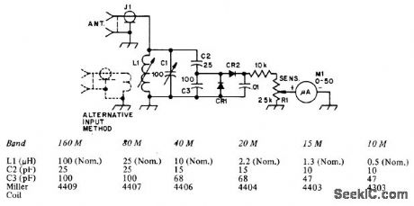
Useful for antenna experiments and ad justments in amateur bands from 160 to 10 meters. Increasing size of pickup antenna increases sensitivity. Far-field measurements are made with alternate input circuit, in which reference dipole or quarter-wave wire cut for frequency of interest is connected to input link. Diodes are 1N34A germanium or equivalent. M1 is 50μA. Table gives values of tuned-circuit components for six amateur bands.-D. DeMaw, A Simple Field-Strength Meter and How to Calibrate It, QST, Aug. 1975, p21-23. (View)
View full Circuit Diagram | Comments | Reading(4972)
TACH_DWELL_METER
Published:2009/6/28 21:53:00 Author:May
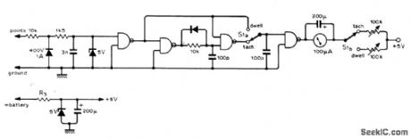
Built around SN7402 NOR-gate IC. Requires no internal battery; required 5 V is obtained by using 50 ohms forR3 in zener circuit shown if car battery is 6 V, and 300 ohms if 12 V. Article gives calibration procedure for engines having 4, 6, and 8 cylinders; select maximum rpm to be indicated, multiply by number of cylinders, then divide by 120 to get frequency in Hz.-N. Parron, Tach-Dwell Meter, Wireless World, Sept. 1975, p 413. (View)
View full Circuit Diagram | Comments | Reading(2256)
| Pages:69/101 At 206162636465666768697071727374757677787980Under 20 |
Circuit Categories
power supply circuit
Amplifier Circuit
Basic Circuit
LED and Light Circuit
Sensor Circuit
Signal Processing
Electrical Equipment Circuit
Control Circuit
Remote Control Circuit
A/D-D/A Converter Circuit
Audio Circuit
Measuring and Test Circuit
Communication Circuit
Computer-Related Circuit
555 Circuit
Automotive Circuit
Repairing Circuit