
Measuring and Test Circuit
Index 77
ATMOSPHERE_NOISE_MONITOR
Published:2009/6/22 23:21:00 Author:May

Tune an unmodified transistor radio to an unused frequency near 540 kHz that's free of broad-cast-station interference; the receiver is used to pick up sferics. The received signal is fed from the receiver's earphone jack through a patch cord to the input jack(J1)of the circuit. The back-to-back audio transformers, T1 and T2, provide a suitable impedance match and signal level when the unit is used with various receivers.Diode Dl rectifies the audio input from the receiver to pulsating dc, which is filtered by C1, R1, and C2 to provide a time constant of several minutes. That dampens out fluctuations in most cases, unless lightning flashes are very infrequent.The voltage appearing at the output of the filter is a function of signal strength transferred by C1.Switch 51 is included to prgvide a convenient way to discharge the capacitors, if adjustments are re-quired during a monitoring session.Integrated circuit U1(one section of an LM324 quad pro op amp)is used as a high input-resis-tance voltmeter. Resistors R2 and R3 determine amplifier gain, and potentiometer R4 is used to ad-just full-scale meter deflection for a suitable voltage level at the input. A value of 1.5 V has been satisfactory for use with several receivers tried, but they can be changed.If the monitor is to be used only as a meter, the milliammeter can be connected directly between R4 and chassis ground, omitting R5, 53, J2, and J3. The latter components provide suitable output for use with a chart recorder having a full-scale range of either 10 mV or 1 mA. The circuit, when powered from a 9-V battery, draws about 1 mA. (View)
View full Circuit Diagram | Comments | Reading(0)
The sensor bridge drive amplifier circuit
Published:2011/7/21 3:03:00 Author:Seven | Keyword: sensor bridge, drive, amplifier circuit
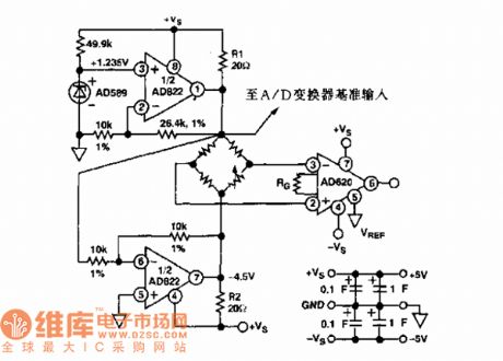
The sensor and AD822 single power supply, power supply forward/backward limit output, low-power FET input computing amplifier circuit. Functions: used in reception office sensor amplifier adjusting, LED preamplifier, medical devices and data collection, etc.
(View)
View full Circuit Diagram | Comments | Reading(628)
The sensor regulation circuit
Published:2011/7/21 3:04:00 Author:Seven | Keyword: sensor regulation circuit
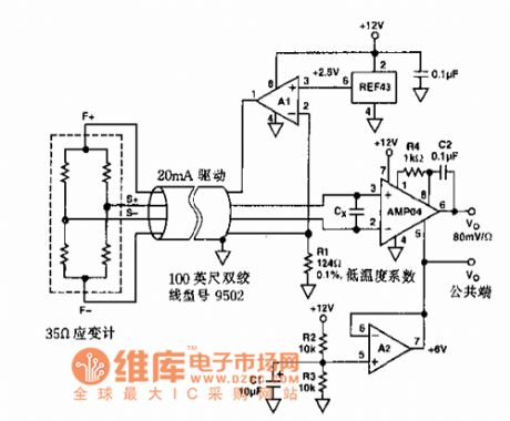
It is used in sensor regulation circuits.
(View)
View full Circuit Diagram | Comments | Reading(483)
REMOTE_TEMPERATURE_SENSING
Published:2009/6/22 23:07:00 Author:May
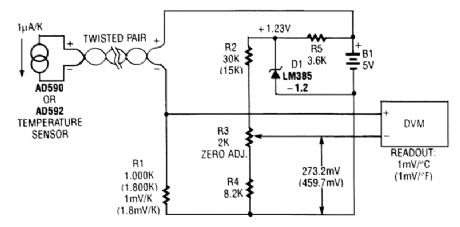
An AD590 or AD592 makes it easy to transmit temperature data over a pair of wires. The circuit produces 1mV/℃ (or 1mV/°F using the values in parentheses). (View)
View full Circuit Diagram | Comments | Reading(2379)
The sensor AD converter circuit
Published:2011/7/21 2:44:00 Author:Seven | Keyword: sensor, AD converter

The figured AD872 is a 12-bit A/D converter. AD8047 is a general voltage feedback computing amplifier, which inputs impedance.
(View)
View full Circuit Diagram | Comments | Reading(515)
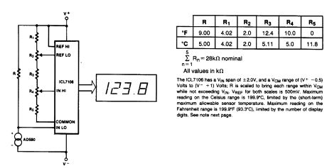
BASIC_DIGITAL_THERMOMETER
Published:2009/6/22 23:05:00 Author:May
View full Circuit Diagram | Comments | Reading(0)
THERMOMETER_FOR_5_V_OPERATION
Published:2009/6/22 23:02:00 Author:May

At the heart of this simple circuit is the well-known type KTY10 temperature sensor from Siemens. This silicon sensor is essentially a temp erature -dependent resistor that is connected as one arm in a bridge circuit here. Preset P1 functions to balance the bridge at 0℃. At that temperature, moving coil meter M1 should not deflect, i.e., the needle is in the center position. Temperature vari-ations cause the bridge to be unbalanced, and hence produce a proportional indication on the meter. Calibration at, say, 20℃ is carried out with the aid of P2.The bridge is fed from a stabilized 5.1-V supply, based on a temperature-compensated zener-diode. It is also possible to feed the thermometer from a 9-V battery, provided D1-D3, R1 and C1 are replaced with a Type 78L05 voltage regulator, because this is more economic as regards to current c onsumption. (View)
View full Circuit Diagram | Comments | Reading(0)
TEMPERATURE_COMPENSATION_ADJUSTER
Published:2009/6/22 23:01:00 Author:May

The circuit shown delivers +10 to -10 mV°/C output using an Analog Devices' AD590 temperature transducer. Rx is a scaling resistor. (View)
View full Circuit Diagram | Comments | Reading(0)
TELEPHONE_LINE_TESTER
Published:2009/6/22 22:59:00 Author:May

The telephone-line tester consists of nothing more than a meter (that's used to measure line voltage in the on- and off-hook state), three resistors (one of which is variable), a pushbutton switch, and a modular telephone connector. When the circuit is connected to the telephone line, a meter reading of 5 to 10 V (when S1 is pressed) indicates that the line is okay. (View)
View full Circuit Diagram | Comments | Reading(0)
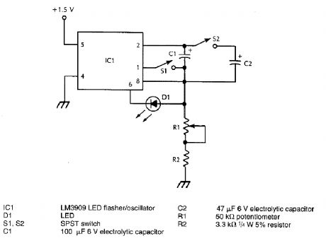
VISUAL_METRONOME
Published:2009/6/22 22:55:00 Author:May
View full Circuit Diagram | Comments | Reading(504)
AUDIBLE_METRONOME
Published:2009/6/22 22:54:00 Author:May
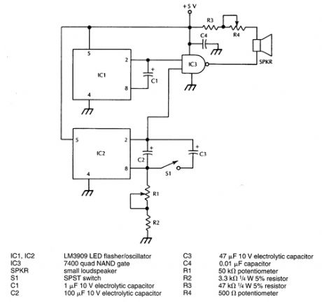
IC1 generates an audible frequency while a variable very low frequency is generated by IC2. R1 sets the metronome rate. The two signals are combined in IC3. (View)
View full Circuit Diagram | Comments | Reading(588)
EIGHT_DECADE_LIGHT_METER
Published:2009/6/22 22:54:00 Author:May

A logarithmic amplifier is adapted to a battery-powered light meter. An LM10, combined op amp and reference, is used for the second amplifier and to provide the regulated voltage for offsetting the logging circuit and powering the bias-current compensation. This can provide input current resolution ofbetter than ±2 pA over 15 to 55℃. Because a meter is the output indicator, there is no need to optimize frequency compensation. Low-cost single transistors are used for logging because the temperature range is limited. The meter is protected from overloads by clamp diodes D2 and D3.Silicon photodiodes are more sensitive to infrared than visible light, so an appropriate filter must be used for photography. Alternately, gallium-ars enide-phosphide diodes with suppressed IR response are becoming available. (View)
View full Circuit Diagram | Comments | Reading(1020)
COLORIMETER
Published:2009/6/22 22:52:00 Author:May

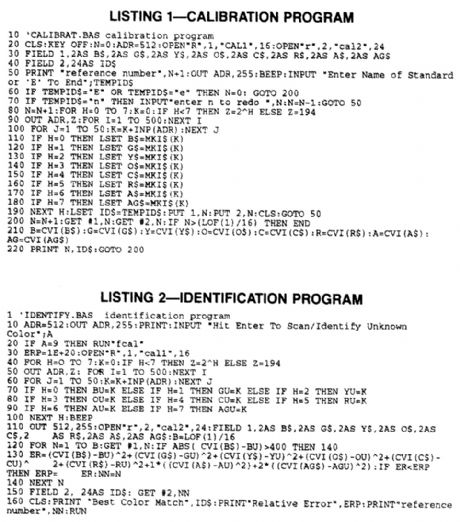
A hardware/software combination activates In turn,one of several LEDs enuts a portion of the visible spectrum .A phototransistor measures the light reflected by the surface being measured,andan 8-bit analog-to-digital converter(ADC) translates the phototransistor’s output into a digital format that the computer can interpret Seven LEDs (blue,aqua,green,yellow,orange,crimson,and red) provride a range of readings across the visible spectrum Lack of spectral continuity among adjacent LED colors could skew results,so the circuit provides built-in compensation for this error.
Two simple BASIC programs control the circuit’s operation. One allows you to define a set of standards by measunng known Color samples and recording the values with an associated name The other program measures unknown samples and provides the best match with the defined standards,as well as a relative error factor. (View)
View full Circuit Diagram | Comments | Reading(3199)
HEARTBEAT_MONITOR
Published:2009/6/22 22:42:00 Author:May

An IR photodiode, which senses IR skin reflectivity as a result of increased blood volume during the periods that the heart forcibly contracts, is used to pick up a signal that is correlated with the heartbeat. A transistor and op amp raise this to a level suitable to trigger logic circuitry or to be displayed on a scope. (View)
View full Circuit Diagram | Comments | Reading(5276)
IR_LASER_LIGHT_DETECTOR
Published:2009/6/22 22:28:00 Author:May
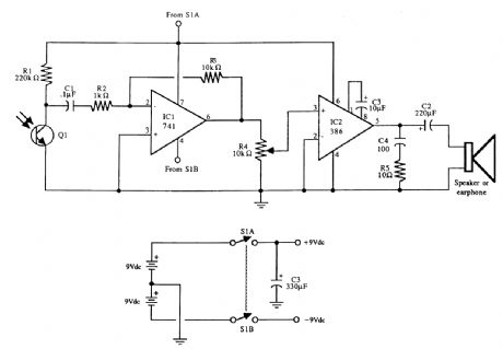
The universal Iaser light detector. The output of the LM386 audio amplifier can be connected to a small 8-Ω speaker or ear-phone. Two 9-V batteries provide power. Decrease R1 to lower sensitivity; increase R3 to increase gain of the op amp (avoid very high gain or the op amp might oscillate). Q1 is an infrared phototransistor. (View)
View full Circuit Diagram | Comments | Reading(2164)
INDUCTANCE_AND_CAPACITANCE_DETERM∶NER_WITH_SWR_BRIDGE
Published:2009/6/22 18:03:00 Author:May


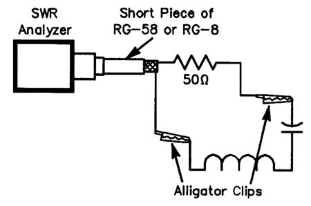
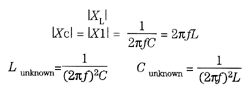
At resonance, the SWR known will be 1:1 with a 50-Q resistance, as reactance is zero. If either L or C isknown: (View)
View full Circuit Diagram | Comments | Reading(622)
BATTERY_MONITOR
Published:2009/6/22 18:01:00 Author:May

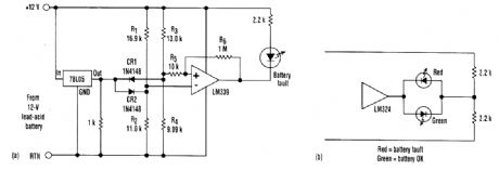
One typical application for the detector involves monitoring a lead-acid battery. It indicates a fault when the battery voltage is outside an 11- to 14-V window. Because the circuit is powered by the battery, the input and reference were switched to keep the comparator inputs within its common-mode range.The circuit's reference is 5.0 V. The resistor values in divider, R1/R2 were selected to produce 5.5 V at the inverting input when the battery voltage is 14.0V. Divider R3/R4 is set to produce 4.5 V at the noninverting input when the battery voltage is equal to 11.0V.When the battery voltage is within the window, the noninverting input is more positive than the inverting input which is clantped at 4.5V by CR2, the noninverting input continues below that, the comparator's output goes low, and the LED turns on. When the battery voltage rises above 14V, the noninverting input is clamped at 5.5V by CR1, the inverting input continues above that, the com-parator output again goes low, and the LED turns on. Resistors R5 and R6 show that hysteresis might be added to this circuit in a conventional manner.If an op amp, such as an LM324 is used as the comparator, two LEDs can be implemented. The green LED will tum on when the battery voltage is within the window, and the red LED tums on when the battery voltage is outside the window. (View)
View full Circuit Diagram | Comments | Reading(2)
ANALOG_CIRCUITRY_CALIBRATOR
Published:2009/6/22 17:47:00 Author:May


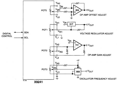
An XICOR X9241 Quad POT IC can be used to digitally adjust four analog circuits, as shown in the example schematic. (View)
View full Circuit Diagram | Comments | Reading(734)
ION_DETECTOR
Published:2009/6/19 4:59:00 Author:May
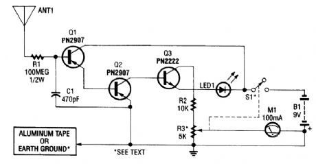
This circuit detects static charges and free ions in the air. It can be used to indicate the presence of ion emissions, high-voltage leakage, static electricity, electrostatic fields, etc. The ground connection is made by either an earth ground or by touching the aluminum foil electrode with your hand.M1 is a 100-μA meter. R3 is a sensitivity control. (View)
View full Circuit Diagram | Comments | Reading(3238)
SIMPLE_HIGH_CURRENT_MEASURER
Published:2009/6/19 4:35:00 Author:May

Testing heavy-load devices with a ten-amp maximum meter can be accomplished with this straightforward meter add-on. If done right, it could be made from a high-current extension cord. J1 and J2 are well-insulated jacks to accept meter probe tips. (View)
View full Circuit Diagram | Comments | Reading(642)
| Pages:77/101 At 206162636465666768697071727374757677787980Under 20 |
Circuit Categories
power supply circuit
Amplifier Circuit
Basic Circuit
LED and Light Circuit
Sensor Circuit
Signal Processing
Electrical Equipment Circuit
Control Circuit
Remote Control Circuit
A/D-D/A Converter Circuit
Audio Circuit
Measuring and Test Circuit
Communication Circuit
Computer-Related Circuit
555 Circuit
Automotive Circuit
Repairing Circuit