Measuring and Test Circuit
FURNACE_FUEL_MISER_1
Published:2009/6/19 3:43:00 Author:May | From:SeekIC

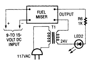
When the circuit is working properly the output circuitry can be checked using a 24-volt step-down transformer, a lk resistor, and an LED. Together those components simulate the load that the Fuel Miser sees during normal operation.
Reprinted Url Of This Article:
http://www.seekic.com/circuit_diagram/Measuring_and_Test_Circuit/FURNACE_FUEL_MISER_1.html
Print this Page | Comments | Reading(3)

Article Categories
power supply circuit
Amplifier Circuit
Basic Circuit
LED and Light Circuit
Sensor Circuit
Signal Processing
Electrical Equipment Circuit
Control Circuit
Remote Control Circuit
A/D-D/A Converter Circuit
Audio Circuit
Measuring and Test Circuit
Communication Circuit
Computer-Related Circuit
555 Circuit
Automotive Circuit
Repairing Circuit
Code: