Measuring and Test Circuit
LOW_COST_FREQUENCY_INDICATOR
Published:2009/7/1 1:29:00 Author:May | From:SeekIC

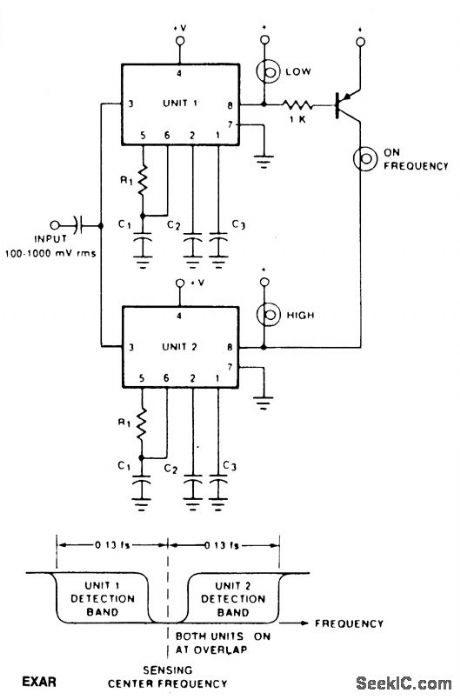
The circuit shows how two tone decoders set up with overlapping detection bands can be used for a go/no go frequency meter. Unit 1 is set 6% above the desired sensing frequency and Unit 2 is set 6% below the desired frequency.Now, if the incoming frequency is within 13% of the desired frequency, either Unit 1 or Unit 2 will give an output. If both units are on, it means that the incoming frequency is within 1% of the desired frequency. Three light bulbs and a transistor allow low cost read-out. The IC is an EXAR 567.
Reprinted Url Of This Article:
http://www.seekic.com/circuit_diagram/Measuring_and_Test_Circuit/LOW_COST_FREQUENCY_INDICATOR.html
Print this Page | Comments | Reading(3)

Article Categories
power supply circuit
Amplifier Circuit
Basic Circuit
LED and Light Circuit
Sensor Circuit
Signal Processing
Electrical Equipment Circuit
Control Circuit
Remote Control Circuit
A/D-D/A Converter Circuit
Audio Circuit
Measuring and Test Circuit
Communication Circuit
Computer-Related Circuit
555 Circuit
Automotive Circuit
Repairing Circuit
Code: