Measuring and Test Circuit
GAS_AND_VAPOR_DETECTOR
Published:2009/7/1 0:34:00 Author:May | From:SeekIC

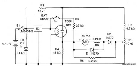
The power drain is approximately 150 mA. IC1 provides a regulated 5-volt supply for the filament heater of the sensor. The gas sensitive element is connected as one arm of a resistance bridge consisting of R4, R7, R8 and the meter Ml with its associated resistors R5 and R6. The bridge can be balanced by adjusting R8 so that no current flows through the meter. A change in the sensor's resistance, caused by detection of noxious gases, will unbalance the circuit and deflect the meter. Diodes D1, D2 and resistor R5 protect the meter from overload while R6 determines overall sensitivity. R2 limits the current through the sensor; R1 and LED1 indicate that the circuit is working, so that you do not drain the battery leaving the unit on inadvertently; R3 and S2 give a battery level check.
Reprinted Url Of This Article:
http://www.seekic.com/circuit_diagram/Measuring_and_Test_Circuit/GAS_AND_VAPOR_DETECTOR.html
Print this Page | Comments | Reading(3)

Article Categories
power supply circuit
Amplifier Circuit
Basic Circuit
LED and Light Circuit
Sensor Circuit
Signal Processing
Electrical Equipment Circuit
Control Circuit
Remote Control Circuit
A/D-D/A Converter Circuit
Audio Circuit
Measuring and Test Circuit
Communication Circuit
Computer-Related Circuit
555 Circuit
Automotive Circuit
Repairing Circuit
Code: