Measuring and Test Circuit
ac_POWER_MONITOR
Published:2009/6/19 4:03:00 Author:May | From:SeekIC

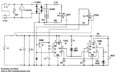
The 0-to 130-V voltmeter and neon AC PWR lamp provide an average indication of the ac power. The fuse and metal oxide varistor(MOV)protect the monitor against overvoltage spikes.Four 1N4004 diodes rectify the ac voltage, generating negative-going pulses twice per cycle(every 8.33 ms for 60-Hz power). Variable-resistor F1 supplies a reduced amplitude sample of these pulses to a missing pulse detector consisting of Q1, IC1, and associated circuitry. As long as the pulse amplitude exceeds the threshold value set by RI, IC1 continually triggers, keeping its output high.When the pulse amplitude drGps below the threshold value, IC1 times out with a time constant set by variable resistor R2 and the 0.47-μF capacitor. R2 is calibrated to read the number of cycles required for a dropout indication. It can be set between 1 cycle(about 17 ms)and 30 cycles(0.5 second).When IC1 times out, its output goes low. This turns on LED1. The low output also triggers IC2, which is configured as a set-reset flip-flop. This turns on LED2. When the voltage returns to normal, IC1 again starts triggering and its output returns high, turning off LED1. LED2, however, remains on until the manual reset button is pressed.The circuit is powered by a 9-V battery and is assembled in a plastic or grounded metal case. No-tice that thqre's no isolation between the ac power line and the monitor circuitry. Be careful to avoid electrical shock when testing the circuitry.
Reprinted Url Of This Article:
http://www.seekic.com/circuit_diagram/Measuring_and_Test_Circuit/ac_POWER_MONITOR.html
Print this Page | Comments | Reading(3)

Article Categories
power supply circuit
Amplifier Circuit
Basic Circuit
LED and Light Circuit
Sensor Circuit
Signal Processing
Electrical Equipment Circuit
Control Circuit
Remote Control Circuit
A/D-D/A Converter Circuit
Audio Circuit
Measuring and Test Circuit
Communication Circuit
Computer-Related Circuit
555 Circuit
Automotive Circuit
Repairing Circuit
Code: